
Extracting maximum value is a tenet of the oil and gas industry. Whether it is a field located deep in the ocean or a rock formation located in the middle of a plain, companies are constantly searching for ways to get as much out of the resources available to them as possible with the tools they have.
Enhanced oil recovery (EOR) is a process being used to help maximize value in existing assets. It involves injecting a substance into a formation to increase the recovery of oil from that formation, such as injecting chemicals into a mature offshore reservoir or carbon dioxide into shale. Regardless of the type used, effective water management is critical to the success of EOR as the injection water must be treated and waste water must be handled and disposed, or recycled for further use.
This feature examines the challenges in water management that companies face with EOR, as well as the strategies and technologies being developed to help tackle them.
Challenges With Chemical EOR Projects
The success of the chemical EOR process depends largely on the quality of the chemical solution injected, particularly if the water will be used for reinjection (Dwyer and Delamaide 2015). Failure to blend the chemicals well enough may cause separation issues, operational issues, and potentially harm a project’s economic viability. Government regulations have limited the use of freshwater sources for these operations, and seawater is available only for offshore projects. So, for onshore EOR projects, produced water is the preferred water source.
Patrick Dwyer, a business development manager at IFP Technologies, said operators must adapt their water treatment strategy to the conditions of the field in which they are operating.
“Before your project starts, you have to make sure that you have a look at what strategy you’re going to deploy and use those water sources,” Dwyer said. “That, to me, is the bulk of the work. The bulk of the cost is the water treatment plan.”
The three chemicals typically used in the chemical EOR process are polymers and water viscosifiers used for mobility control; surfactants, which reduce the interfacial tension between the oil and the water; and alkalis, which reduce the adsorption of the surfactant. These chemicals can be used together or separately (Dwyer and Delamaide 2015).
Each chemical can be difficult to handle, but Dwyer said the biggest difficulty an operator faces with chemical EOR is the use of produced water to mix down a polymer. Produced water that contains a polymer is more viscous, which may potentially slow the water treatment process (Thomas, Gaillard, and Favero 2012). Surfactants can cause emulsion problems and issues with separation. Polymers and surfactants are sensitive to salinity and hardness, so any variance in those two variables may negatively impact chemical injection.
Polymers may be a source of fouling for heater treaters, which are commonly used for oil/water separation, by precipitating on their components and causing hot spots. This precipitation could also cause the failure of these components, thus increasing operating costs. Dwyer said polymer mixing is highly sensitive to shear and that it is important to ensure the equipment being used at the surface facility is as “friendly to the polymer” as possible. This means using pumps with low shear, like plunger pumps, instead of centrifugal pumps.
Produced water from chemical EOR operations often gets recycled for other uses. However, in cases where that water must be disposed, companies face a complex task. Surfactants in particular can have a negative impact on the surrounding environment when disposed, and Dwyer said an increase in the volume of water needed for chemical EOR processes in recent years makes disposal even more difficult.
“When we were talking about volumes 10 or 20 years ago, those totals were relatively small [compared] to what they are today, so now people are paying attention to what, exactly, is going down the well because there’s a heck of a lot more that they’re doing. That’s why I think everybody’s paying more attention,” Dwyer said.
Lisa Henthorne said a problem facility engineers face in developing produced-water treatments is accounting for the unknown quality of the produced water, and the ways in which it may change over time. Henthorne is senior vice president and chief technology officer at Water Standard, a water treatment specialist company.
“Offshore, where the space and weight limits [of surface facilities] are fixed parameters, the potential for emulsions that require rigorous oil/water separation treatment creates a tenuous design challenge,” she said. “These uncertainties, coupled with the environmental concerns of discharging injection polymers, require expert know-how and risk-mitigation measures in order to make these projects viable.”
Environmental Concerns
A critical concern with handling produced water in chemical EOR offshore is the potential impact on the marine environment in fields where surface facilities were not initially designed for produced-water chemicals management (Najamudin et al. 2014). Surfactant can be toxic to local wildlife, and the low biodegradation property of polymers makes them a potential hazard.
Petronas, the Malaysian national oil company, has been at the forefront of chemical EOR developments. In December, it began production from the first full-field, vessel-based chemical EOR project at Angsi, a mature field off the coast of the Malaysian peninsula it co-owns with ExxonMobil. The field requires 160,000 BWPD for its operations.
Before startup, Petronas tested its water management strategy in a field located in the southern part of the Malay Basin. The project contained one central processing platform and four drilling platforms. Waterflooding accounted for 90% of the field’s production mostly because low aquifer support necessitated the use of waterflooding to support production and pressure maintenance. Chemical EOR was also used to increase oil recovery.
The company tested the toxicity, bioavailability, and biodegradability of its produced water to characterize and predict the potency of the effects of chemical EOR residual substances toward the environment. From there, it would determine the strategies needed to mitigate those effects.
At the time of testing, the produced water was being treated offshore for overboard disposal. It contained several residual high-molecular weight components with specific features that made treatment difficult, and its composition was approximately 3%–15% surfactant and 28%–44% polymer.
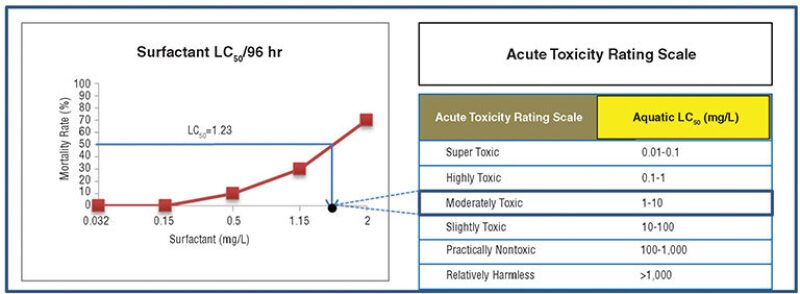
An acute toxicity test performed on local fish revealed a 100% survival rate against polymer concentration ranging from 320 mg/L to 500 mg/L, suggesting that the median level of the lethal concentration (LC50) is higher than 500 mg/L. The LC50 value for surfactant was 1.23 mg/L, suggesting that it is a more toxic substance (Fig. 1). At 5 mg/L, the surfactant produced a 100% mortality rate within 12 hours. At 300 mg/L, it took only 2 hours to reach a 100% mortality rate.
In a dilution modeling study, surfactant released into the environment reached concentrations below toxicity levels within 500 m of the release point. A few chemicals were found beyond the 500-m mark, but those chemicals were highly degradable and unlikely to have a negative environmental impact (Najamudin et al. 2014).
The systems designed for treating produced water from waterflooding did not meet the requirements for treating water breakthrough from chemical EOR flooding. Petronas determined that the installation of new equipment and the implementation of new treating processes would be too expensive, and other applicable commercial technology to treat polymer in produced water offshore is limited, with no case studies or full-field applications. So, it looked for a less difficult method to mitigate the problem.
One strategy it examined was the addition of coagulants at the produced-water stream outlet to initiate chemical precipitation of the polymer before discharging the produced water. Further study on the coagulant showed that it had a polymer removal rate as high as 98% in produced water.
However, this approach was problematic, primarily in that it was too specific of a treatment to cover all possible conditions that can occur in production. The efficiency of the treatment depended too much on uncontrollable factors, such as the polymer’s concentration, its molecular weight, and the volume of produced water. In addition, the method produced a high volume of waste that was difficult to treat and created a significant logistical issue with offshore application.
Another strategy considered was the use of polymer separation and degradation methods like chemical precipitation, mechanical precipitation, advanced oxidation, hydraulic shearing, and thermal degradation. At laboratory scale, some of those methods were shown to have a 99.5% removal rate.
Membrane De-Aeration Technology
Conventional surface water-injection facilities use some form of media filtration and de-aeration to reduce the partial pressure of the oxygen in water. The de-aeration process usually involves vacuum towers and chemical oxygen scavenging with sodium bisulfite, and the water is treated to remove sulfate prior to injection. This helps prevent barium and strontium precipitation in the reservoir and reduces the chances of souring (Henthorne and Wodehouse 2012). But vacuum pumps have high maintenance costs, particularly to ensure that oxygen does not enter the system through a seal or a pipe joint.
Henthorne said the space needed for vacuum pumps makes them tough to install. “Because these kits need a considerable amount of space and weight, anywhere else where you can save weight and space in the overall package will be an enabler, like in an ancillary system like the de-aeration unit,” she said.
Last year Water Standard partnered with Membrana to develop Liqui-Cel, a compact membrane de-aeration contactor that assists operators in chemical EOR projects where the existing facilities do not have enough space for a vacuum tower. The contactor’s modular design consists of small skids and multiple pressure vessels arranged in parallel to separate dissolved oxygen from water. It has thousands of microporous polypropylene hollow fibers knitted into an array and wound around a center tube (Fig. 2), and because its hollow fiber membrane is hydrophobic, seawater does not penetrate into the membrane pores.
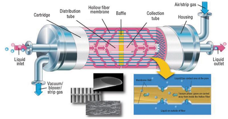
The transfer between the seawater and the nitrogen sweep gas phase is governed by the partial pressure difference of oxygen between the two phases. The degassing surface area per unit volume is greater than that of a vacuum tower, and this difference allows for a smaller-sized system (Henthorne et al. 2015).
Water Standard tested the commercial viability of this technology for offshore oil and gas applications, conducting an evaluation of the size, weight, capital cost, and operating cost for membrane de-aeration against conventional vacuum tower de-aeration at a seawater intake facility near the coast of northeast Florida. The tests used gas-permeable membrane contactors that separated dissolved oxygen from water. Two other membrane contactors provided redundancy in case of fouling.
The first phase of field testing examined the performance of the membrane contactors in pure water service. Water Standard ran 15 unique experiments at a length of at least 10 hours per experiment. It compared the dependent variables for each experiment with the membrane manufacturer’s expected results as generated from simulation software.
At 1 micron pre-filtration, there was no relative loss in the expected percentage of oxygen removal performance, nor was there an increase in membrane differential pressure. However, there was a point of diminishing returns when the nitrogen sweep gas flow rate was greater than
1.3 normal m3/h. Higher flow rates saw only slight improvements in the oxygen removal performance. This meant that it was possible to reduce nitrogen consumption to 0.43 normal m3/h per contactor with only a slight decrease in oxygen removal performance if the nitrogen supply is scarce (Henthorne et al. 2015).
The development of the membrane de-aeration technology’s scope required certain assumptions. The high-pressure injection booster pumps were eliminated from the system because a dry air supply was presumed to be available on any existing facility. In addition, the research team acknowledged that the membrane de-aeration system did not require an oxygen scavenger chemical. However, Henthorne said it was still included in the system’s economic and weight assessments of the contactor as a conservative approach.
“Because the technology is new to the oil and gas industry, some operators may require a backup, or safeguard, system to ensure the oxygen risks are mitigated sufficiently until this technology is well-proven offshore,” Henthorne said.
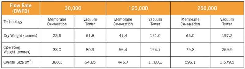
Water Standard’s performance tests compared multidisciplinary engineering and design for each technology at specific injection flow rates, producing detailed 3D models, material takeoffs, and weight reports for each design. The results showed that the membrane de-aeration technology had a noticeable impact: Its dry and operating weight was 60%–70% lighter and its size was 30%–60% lower (Table 1) than vacuum towers.
The tests accounted for the sensitivity of the membranes to varying levels of suspended solids and organic foulants in the feedwater, an unknown quantity long associated with the application of membrane contactors in offshore water-injection installations.
“Membranes will always behave as a common filter if given the chance,” Henthorne said. “That is, they are like a sheet of plastic that is permeable to certain dissolved species—like water or oxygen—but will prevent larger things like particles of suspended matter from passing through. If you have any particles in the water, the membrane will unwittingly filter those out too, thereby plugging the surface area that is needed to remove the species you want to remove.”
The membranes’ performance and fouling variables were closely monitored at different levels of filtration. The independent variables monitored were inlet oxygen concentration, inlet seawater temperature, and the level of filtration between 1 micron and 20 micron, while the dependent variables monitored were outlet dissolved oxygen concentration and membrane differential pressure.
Running the cartridge with a 20-micron filter, the contactor’s oxygen removal performance decreased from 7 parts per billion to 30 parts per billion during the 250-hour running time. After that, the contactor was shut down. Condensation also built up on the fibers of the contactors and remained for 24 hours during the testing period, resulting in a short-term increase in outlet dissolved oxygen concentration by 10 parts per billion. A brief purge with nitrogen sweep gas removed this condensation.
The tests showed that, with the 20-micron filter, the contactors were subject to performance losses depending on the quality of the seawater fed into the system. For this particular test, iron in the feedwater was considered the most likely cause of fouling. Caustic and acid chemical cleaning restored the contactor’s performance and reversed the fouling.
CO2 EOR in Shale Plays
With local and state governments limiting the use of freshwater sources for hydraulic fracturing operations, companies must find new ways to extract resources from shale formations.
Waterflooding is ineffective in unconventional fields, but gas flooding with carbon dioxide (CO2) has become an increasingly popular method of extending the life of shale plays. CO2 EOR is a process in which CO2 mixes with tight oil to lighten its volume, detaching the oil from the rock surface and allowing it to flow more easily. The volume of produced water derived from this operation can be significant, and the industry is trying to determine if this water can be a valuable resource in future fracturing projects.
In 2012, a team from the University of Illinois at Urbana-Champaign released a report examining the potential for reusing produced water from oil recovery operations in the Illinois Basin. According to the report, Illinois’ waterflood EOR operations produced 138 million bbl of produced water from 2001 to 2006, with an average water/oil ratio of 41.2. In 2008, the 43 counties that produced oil in Illinois also produced an estimated 346 million bbl of water. Approximately 256 million bbl/yr of water is disposed into something other than oil-producing formations (Knutson et al. 2012).
The research team considered slow and fast water production rates from CO2 EOR to estimate future volumes of produced water. For the slow rate, EOR was presumed to continue at a constant rate until 10% of the original oil in place was obtained, after which the water flow rate would be calculated by dividing the total volume of water available by the duration of oil production. Based on the 2008 production rate, this slower water production rate was estimated at
32 million bbl/yr. For the fast rate, oil production was presumed to continue at a constant rate until all available water was extracted—this was estimated at 238 million bbl/yr.
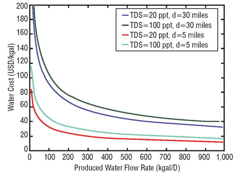
The transportation of produced water can be a significant complication with fracturing operations. Fig. 3 shows the overall costs for the treatment and transport of water with total dissolved solids values ranging from 20 g/L to 100 g/L and pipeline distances ranging from 5 miles to 30 miles. At smaller flow rates, the water costs increase significantly.
For Further Reading
OTC 24804 Chemical EOR Produced Water Management at Malay Basin Field by K. E. Najamudin, N.H. Halim, and I.K. Salleh et al., Petronas.
SPE 154281 The Science of Membrane Technology to Further Enhance Oil Recovery by L. Henthorne and J. Wodehouse, Water Standard.
SPE 174532 Offshore IOR/EOR Implementation Through Weight and Footprint Reduction by L. Henthorne, S. Van Pelt, and H. Johnson, Water Standard.
SPE 174537 Produced Water Treatment—Preparing for EOR Projects by P. Dwyer and E. Delamaide, IFP Technologies.
Knutson, C., Dastgheib, S. A., and Yang, Y. et al. 2012. Reuse of Produced Water from CO2 Enhanced Oil Recovery, Coal-Bed Methane, and Mine Pool Water by Coal-Based Power Plants. Final report, Contract No. DE-NT0005343, US DOE, Washington, DC (July 2012).
Thomas, A., Gaillard, N., and Favero, C. 2012. Some Key Features to Consider When Studying Acrylamide-Based Polymers for Chemical Enhanced Oil Recovery. Oil & Gas Science and Technology 67 (6): 887–902.