
The SPE Separations Technology Technical Section (STTS) is excited to launch “The Savvy Separator,” a series of articles that will present helpful design know-how, lessons learned, and solutions for separation problems. The articles will stem from our members' experience.
Although the section's board members will initially provide the articles, we encourage our members to submit articles for review or suggest topics. We will also look at the questions being asked on the section’s message board to identify topics of interest (http://connect.spe.org/separationstechnology/home).
The main goal of the STTS is knowledge transfer. Toward this purpose, the section has established an annual webinar series and a special session at the SPE Annual Technical Conference and Exhibition.
We welcome your feedback on the articles and look forward to the sharing of your own knowledge.
—Hank Rawlins, eProcess Technologies
Rawlins is the chairman of the STTS and may be reached at hrawlins@eprocess-tech.com.
Separators range from a simple empty vessel to one packed with internals such as cyclonic inlets and mist eliminators, perforated baffles, and passive and electrostatic media. A separator generally serves a dual purpose of cleaning up gas and liquids. Some internals, however, affect the separator's gas- and liquid-handling capability because of their effects on the liquid level. In this article, the interdependency of cyclonic inlets, cyclonic mist eliminators, and liquid level is highlighted.
Gas/liquid separators have evolved over the past 15 years to improve efficiencies and reduce the size and weight of the separator. Mark Bothamley’s series of articles in Oil and Gas Facilities (2013a, 2013b, and 2013c) summarized general separator design and the sizing of internals.
A major factor to be considered in the design of a cyclonic separator is the pressure drop (energy usage) associated with its operation. Internals such as mesh and vane eliminators and inlet vane diffusers result in a relatively low pressure drop and, thus, have a relatively small effect on the liquid level.
Because of the associated high pressure loss, some internals such as inlet cyclones and demisting cyclones affect the liquid level in the separator, which in turn affects degassing, level control, liquid/liquid separation, and surge control. An understanding of the interdependency of the internals and the liquid level is required in order to properly design, troubleshoot, and debottleneck a separation system.
Inlet Cyclone Design
Inlet cyclones separate the gas and liquid phases by inducing a spin to the fluids, with the heavier liquid phase moving to the cyclone’s perimeter and the gas phase moving to the interior (Chin et al. 1999). The cyclones range from a simple empty cylinder to ones packed with turbine blades (Figs. 1 and 2). A common feature is a top gas outlet and a bottom liquid outlet, which is typically sealed in the liquid phase. The sizing of cyclones is dictated by the energy, or pressure, required to push the gas out of the top and the liquid out of the bottom.
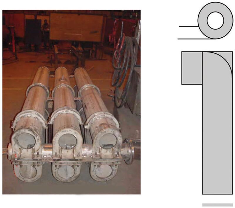
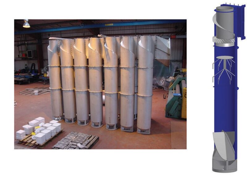
Fig. 3 shows the factors related to the pressure balance in the separator. P1 is the pressure inside the cyclone experienced by the gas and liquid phases, P2 is the vessel pressure, ΔPGas is the gas pressure loss, ΔPLiq is the liquid loss, H is the liquid level in the vessel, and ΔHI is the difference in the liquid levels inside the cyclone and the vessel.
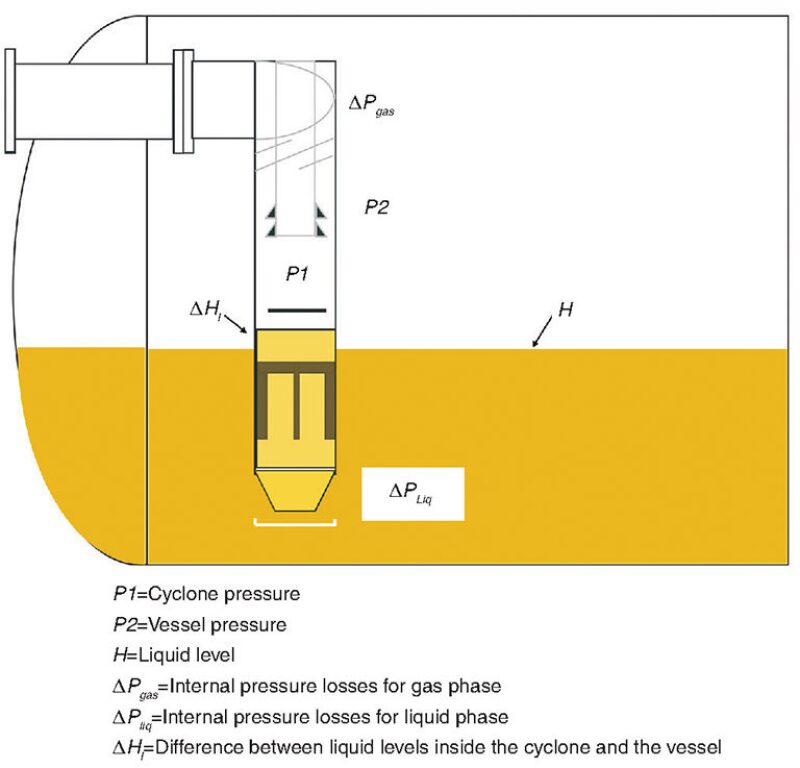
For simplicity, a single liquid phase is assumed. Depending on the cyclone’s design, the gas phase must overcome the pressure losses (ΔPGas ) to exit the top, and the proximity of the top outlet to the vessel wall may contribute additional backpressure.
The pressure loss typically ranges from inches of water for simple cyclones to approximately 1 bar for cyclones with internals. As gas rates increase, P1 must increase to overcome higher pressure losses. Similarly, the liquid phase must overcome a drop in internal pressure to exit the bottom of the cyclone. As the liquid rate increases, P1 and/or the liquid level inside of the cyclone must increase to push the liquid out of the bottom, overcoming the liquid loss. The liquid loss includes the liquid static head from the liquid level in the vessel (although this is counterbalanced by the liquid head inside the cyclone).
The pressure balance in Fig. 3 is represented by the following equations, in which gas hydrostatic head differences are ignored:
P1 - ΔPGas = P2 (1)
and
P1 + ρLg ΔHI - ΔPLiq = P2 (2)
where ΔHI is the difference in liquid levels inside the cyclone and the vessel and ρL is the liquid density.
Assuming the liquid rate is constant, the pressure (P1) inside of the cyclone will increase and push down on the liquid as gas rates increase. Gas blowby is a condition when the gas rate is high enough to blow out through the liquid outlet and into the vessel liquid volume. The separator problems that may result from blowby are the following:
- Foaming
- Loss of level control
- Gas carry-under/liquid carry-over to the next vessel
Recovery from blowby may require a temporary reduction in production rates or, in extreme cases, a process shutdown to allow the resealing of the bottom of the cyclone.
Assuming the gas rate is constant, the liquid level inside of the cyclone increases to push more liquid out of the bottom of the cyclone as the liquid rates increase. Liquid carry-over is a condition when the liquid flows out of the top gas outlet and into the gas phase of the vessel, possibly resulting in a higher liquid loading to the mist eliminator.
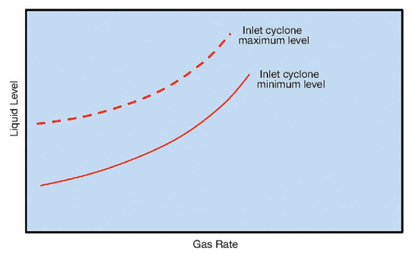
The liquid level plays an important role in the operating range of an inlet cyclone and in the avoidance of gas blowby and liquid carry-over. Fig. 4 shows the trend in the vessel operating liquid level range as a function of the gas rate for a given liquid rate. The dashed curve is the maximum liquid level allowed to avoid liquid carry-over, and the solid curve is the minimum liquid level allowed to avoid gas blowby. The vessel’s liquid level operating range, which includes normal, low/high alarms, and low/high shutdown levels, must fall between the two curves. In the case of a higher liquid rate, both curves shift downward.
Pressure also affects the design of the inlet cyclone. For the same gas and liquid mass rates, the difference in liquid levels inside the cyclone and the vessel (ΔHI) will decrease as the pressure increases.
When designing a separator with these cyclonic internals, it is important to cover the entire range of operating conditions because of the effect the internals can have on the pressure balance, including
- Minimum/maximum gas and liquid rates
- Minimum/maximum gas/oil ratio
- Operating pressure
The process conditions can differ significantly in early, middle, and late field life. If certain combinations are missed, the design may not work under all conditions.
Of course, the real world is not as ideal as described above. For example, a two-phase distribution becomes important as premature blowby and carry-over may occur with multiple cyclones. The inlet piping geometry plays an important role in the cyclone’s ability to handle fluid spinning and maldistribution at the inlet. Simple cyclones with a low pressure drop are more susceptible to maldistribution from poor piping geometry. Mal-distribution should be considered in the estimates of blowby and carryover levels.
Also, there is usually some level of gas carry-under from the inlet cyclones that affects the liquid density. In some cases, more gas may be entrained out of the bottom of the cyclone as the liquid level decreases before the blowby level is reached. The actual operating experience will determine the critical liquid level at which the cyclone will remain sealed for satisfactory performance of the separator.
Demisting Cyclone Design
In a typical demisting cyclone installation for horizontal separators (Fig. 5), the horizontal flow cyclones are encased in a gas box with a drain tube sealed in the liquid below the shutdown level (Stewart et al. 1988). The same cyclonic separation principle and sizing for the inlet cyclone applies.
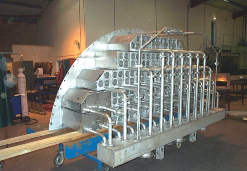
Fig. 6 shows the cyclone pressure balance. P2 is the vessel pressure, P3 is the pressure inside the cyclone gas box experienced by the liquid phase, and P4 is the gas pressure just downstream of the cyclone outlet. For simplicity, we will assume a single liquid phase. The loss of pressure from P3 to P2 is due to the energy required to spin the fluids and push the liquid into the drainage box. The gas phase may experience an additional pressure loss as it flows out of the gas exit, for example, because of a lip on the gas outlet.
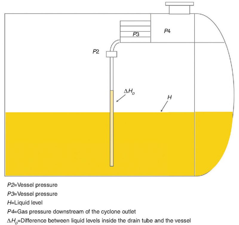
Based on this information, one may conclude that P4 < P3 < P2. Because P3 is less than P2, the liquid height in the drain tube must be higher than the liquid height in the vessel to provide the hydrostatic head to push the liquid out. The head requirement (ΔHD) can range up to several feet. For any demisting device, the drain pipes should be designed for a self-venting flow with a Froude number of less than 0.3 (McKetta 1991). The Froude number is a dimensionless parameter measuring the ratio of fluid inertia to the gravitational force.
Ignoring the gas head, the following equation describes the process:
P2 = P3 + ρLg HD (3)
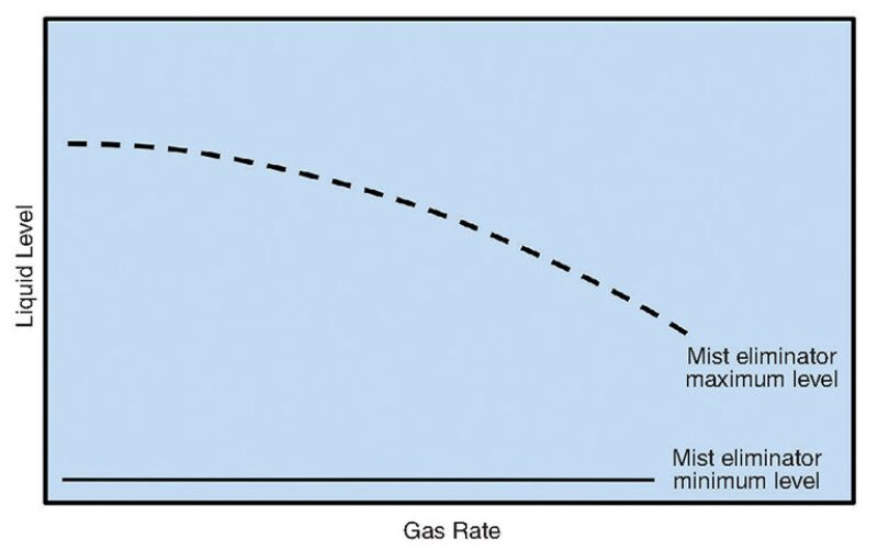
If pressure losses are too high due to high gas rates or liquid loading, P3 can become so low that the drain tube acts as a siphon, leading to massive carry-over. Fig. 7 shows the trend in the maximum liquid level as a function of the gas rate. As with inlet cyclones, ΔHD will decrease with increasing pressure for the same gas and liquid mass rates. Maldistribution is usually not a concern with these high pressure drop intervals: Entrained gas will affect liquid density, hence the drainage height.
The minimum liquid level is dictated only by the need to keep the drain tube sealed in the liquid phase. The location of the drain leg relative to the liquid outlet needs to be considered, especially in revamps in which a high liquid outlet velocity may lead to a vortex. This could create a low pressure drop and suck the liquid out of the drain leg if the drain leg is above the liquid outlet.
The vortex can also occur with poor antivortex breakers. The design needs to also account for solids that could block the drain leg.
Operating Liquid Levels
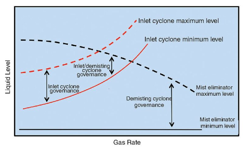
Fig. 8 combines the operating liquid levels for a typical design of a vessel that has both inlet cyclones and demisting cyclones. The three areas of operation are
- Inlet cyclone governance. At low gas rates, the minimum and maximum liquid levels are governed by the inlet cyclone. The liquid level must be lower than the liquid carryover curve and higher than the gas blowby curve.
- Inlet and demisting cyclone governance. At higher gas rates, the drainage head of the demisting cyclones comes into play and dictates the maximum liquid level. The gas blowby curve of the inlet cyclone dictates the minimum liquid level.
- Demisting cyclone governance. At even higher gas rates, the drainage head of the demisting cyclones dictates the liquid level settings. The liquid level must seal the tube at a low level and be below the maximum level to allow for drainage.
Poor level control, liquid carry-over or gas carry-under into the next vessel, and pump gas locking are all signs of poor separation efficiency. Understanding how the inlet and demisting cyclones are affected by the liquid level and the knock-on effects of improper level setting will improve separator troubleshooting.
Other factors, such as process condition changes, flow regime, liquid surface re-entrainment, droplet size distribution, and foaming can contribute to poor separator efficiency. However, after checking and eliminating the instrumentation as a cause, determining whether the internals are properly designed for the actual operating process conditions is generally the first task on a troubleshooting list.
Atypical Design Considerations
There are several examples of operating conditions that can challenge liquid level settings. Firstly, the vessel liquid level may need to be lower than the blowby level of the inlet cyclone. High retention or reaction time requirements between levels may require low alarm or shutdown levels. High gas rates require low liquid levels for a high mist eliminator drainage head. Liquid sloshing due to platform motion results in low levels at the inlet cyclone location.
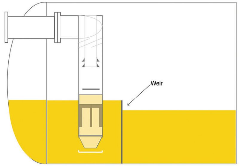
A possible solution to this problem is to place a weir just downstream of the inlet cyclones to maintain a liquid level above the blowby unit, but below the liquid carryover limit as shown in Fig. 9. Liquid sloshing is generally not a factor for short spacing. The disadvantages of this design are the possible buildup of solids behind the weir, impeded vessel access, and an additional vessel drain in the inlet section.
Secondly, for a high gas rate, a large mist eliminator drainage head may be required. A solution to this problem is to install an overflow weir just upstream of the drain tube that can maintain a lower level for the cyclones. The downsides to this solution are added controls and complexity, vessel access, and sloshing of the main part of the vessel.
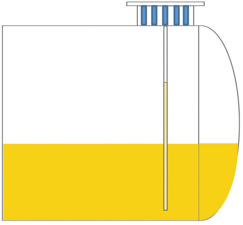
Another possible solution is the use of a mist eliminator in the gas outlet/dome (Fig. 10), where the entire gas space can be used for the drainage head. However, potential downsides to this solution are the added size of the nozzle and flow maldistribution across the mist eliminator, although this is not a major concern due to the high pressure drop across the cyclones.
Conclusion
Three operating regions in which the liquid level settings are dictated by the inlet cyclones, the demisting cyclones, or both have been identified. Understanding the interdependency of internals and liquid level will improve the designing, troubleshooting, and debottlenecking of a separation system.
The second part of “The Savvy Separator” series, which discusses the effect of inlet geometries on flow distribution, will appear in the August issue of Oil and Gas Facilities.
I would like to thank Ed Grave, Victor van Asperen, and Jimmie Riesenberg, members of the STTS, for their valuable contributions to this article.
For Further Reading
SPE 50685 A New Approach to Gas-Liquid Separation by A.C. Stewart, N.P. Chamberlain, and M. Irshad, Kvaerner Paladon.
SPE 56705 Chemical Defoamer Reduction with New Internals in the Mars TLP Separators by R.W. Chin, CDS Separation Technology et al.
Arnold, K.E. ed. 2007. SPE Petroleum Engineering Handbook, Volume III, Facilities and Construction Engineering. Richardson, Texas: SPE.
Bothamley, M. 2013a. Qualifying Separation Performance in Gas/Liquid Separators. Oil and Gas Fac 2 (4): 21–29.
Bothamley, M. 2013b. Qualifying Separation Performance in Gas/Liquid Separators—Part 2. Oil and Gas Fac 2 (5): 35–47.
Bothamley, M. 2013c. Gas/Liquid Separators—Part 3: Quantifying Separation Performance. Oil and Gas Fac 2 (6): 34–47.
McKetta Jr., J.J. 1991. Encyclopedia of Chemical Processing and Design: Volume 38, Piping Design. New York City: CRC Press.

Robert Chin is a cofounder and past chair of the SPE Separations Technology Technical Section, past chair of the SPE Gulf Coast Section’s Projects, Facilities, and Construction study group, a member of the SPE Annual Technical Conference and Exhibition’s Projects, Facilities, and Construction paper selection committees, and the author of Chapter 3, “Oil and Gas Separators,” in the SPE Petroleum Engineering Handbook, Volume III, Facilities and Construction Engineering. He has more than 30 years’ experience in the oil and gas industry, mainly with Shell. Chin joined Shell in 1981 and advanced research on multiphase flow, leak detection, and separations. He left in 1999 to form a separator design and supply company. He returned to Shell in 2006 and led teams on facilities for enhanced oil recovery and subsea processing research and development. Chin retired from Shell last year. He is a cofounder of Padden Engineering and a consultant in the industry. He may be reached at r.w.chin@sbcglobal.net.