Poor well performance and downhole failures have a significant effect on operator profitability. To combat this, operators spent nearly USD 10 billion in 2013 on time-consuming and costly well interventions to retrieve and repair completions hardware.
A major factor contributing to the high cost of interventions is the lack of reliable information about the current condition of the downhole equipment. The ability to accurately visualize equipment in a well allows an operator to execute the remedial work plan more efficiently, thus saving time and money.
Several methods are available for visualizing hardware downhole. The oldest technique uses a block of lead lowered into the well to take an impression of the object. While fast and inexpensive, the impression is often difficult to interpret.
A more recent technology involves using ultrasonic imaging to produce an image of an object inside a fluid-filled well. However, this technique requires a knowledge of the exact specifications of the well fluid at the investigation depth to determine the speed of sound in the fluid. Furthermore, if the well fluid contains too many gas bubbles or suspended particles, then an excessive absorption and scattering of the ultrasonic beam will result in poor image quality.
As a third option, optical cameras provide images in well fluids that are transparent to visible light or in gas-filled wells, but even small traces of oil or particulates will distort the images. As a result, operator costs increase not only for cleaning the well, but also for changing out the original well fluid with an optically transparent fluid before running the camera.
The shortcomings of these methods led to a joint industry project to investigate the use of downhole X-ray imaging. However, common applications of X-ray imaging in the medical and security fields require access to both sides of the object, which is generally not possible in an oil well. Instead, a new technique has been developed using X-ray backscatter imaging.
In backscatter imaging, both the X-ray source and detector are positioned on the same side of the object of interest. Emitted from the source toward the object, the X-ray photons pass through the opaque fluid, scatter within the fluid and from the object, and pass back through the opaque fluid to enter the detector. A conventional backscatter image is obtained by recording the photons scattered by the object.
However, the object of interest inside an oil well is usually metal, often steel or another highly dense material, and these materials readily absorb photons. Therefore, the signal received in the detector is mainly composed of photons that have been scattered by the fluid, which rules out conventional X-ray backscatter imaging.
Thus, a team of physicists and imaging experts at Visuray developed a novel technique called fluid-based surface imaging for converting backscattered photons from the fluid into a visual representation of the object. This patent-pending technique has been implemented in the Visuray VR90 wireline tool to give operators the ability to reliably visualize downhole equipment, even in untreated production fluids, consequently reducing rig time and substantially cutting operator cost.
Fluid-Based Surface Imaging
This technique is founded on the assumption that photon scattering originates primarily in the fluid and that an object contributes a negligible amount to this scattering. It also assumes that the amount of scattering recorded depends on the amount of fluid between the object and the detector that is illuminated by the beam and within the field of view of the detector.
In an experiment to validate these assumptions, measurements of the amount of backscattered photons were made with an X-ray source and detector placed on one side of a water-filled tank with thin walls. The width of the tank was varied between 0 cm and 10 cm in 1-cm increments. Measurements were repeated with a thick steel plate placed flush on the opposite side of the tank.
A comparison of the results of the two experiments showed that the scattering from the plate made up less than 10% of the total scattering for tank widths greater than 2 cm. Furthermore, the magnitude of scattering continued to increase with increasing tank width. Therefore, the amount of scattering detected is a proxy for the distance between the source/detector setup and the steel plate. Fluid-based surface imaging uses this principle to reconstruct the surface of an object from spatial variations in the scattered intensity from the fluid.
The principles of this technique are illustrated in Fig. 1. A step-shaped object is immersed in a liquid medium and illuminated by a broad-beam X-ray source. The imaging system consists of an X-ray area detector that is divided into many pixels and a pinhole to limit the field of view of each pixel.
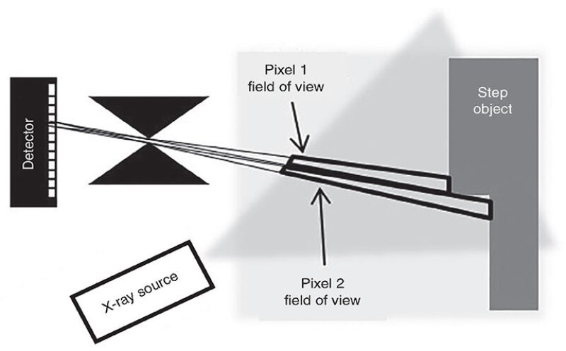
Pixel 1 views the part of the step object that is closest to the detector, while Pixel 2 views the part of the step object that is farthest away. Thus, the amount of X-ray-illuminated fluid that lies within the field of view of Pixel 1 is less than the amount of illuminated fluid that lies within the field of view of Pixel 2.
Consequently, Pixel 1 will register less scattered intensity than Pixel 2, creating a contrast between the two points of the object in the image. The differences in measured intensities from each pixel are then used to re-create the surface topography of the step.
Implementation in Tool
Performing X-ray backscatter imaging in oil wells required the development of a wireline tool containing all the components of the imaging system. The resulting tool, the VR90, measures 8.38 m in length (27.5 ft) with a diameter of 9.2 cm (3⅝ in.). It operates at ambient temperatures of up to 150°C (300°F) and can withstand pressures of up to 1380 bar (20,000 psi). It is compatible with tractors, strokers, and coiled tubing. The tool can be run on all types of electric wireline, either centered or eccentered in the well.
A custom-built thermionic X-ray tube is installed along the tool axis and shielded so that X-rays are emitted as a broad beam primarily through the bottom nose. The X-ray tube operates at a voltage of 180 kV and an electron beam current of 1 mA. The specially designed X-ray detector has six individual detector tiles, each divided into 128-by-128 pixels with a pixel size of 100 µm by 100 µm. Each detector tile has its own 350-µm diameter pinhole to direct backscattered X-rays onto the tile.
The six tiles and pinholes are arranged azimuthally around the X-ray tube, providing the tool with a good overall field of view while maintaining high spatial resolution. Data from all six tiles are combined to create a single composite image spanning the entire field of view. The composite image may be displayed as a 2D depth map image or rendered as a 3D surface reconstruction.
Laboratory and Field Testing
The VR90 wireline tool was installed in a mock-up of an oil well: a 30-cm-tall, 15.8‑cm inner-diameter steel casing filled with fluid. A variety of different well intervention scenarios were tested, including an investigation of the condition of fishing heads, inspection of subsurface safety valves for scale and damage, and identification of lost objects for fishing. In addition, various potential production fluids, such as water, brine, oil, water with suspended rust particles, and sand in water, were tested.
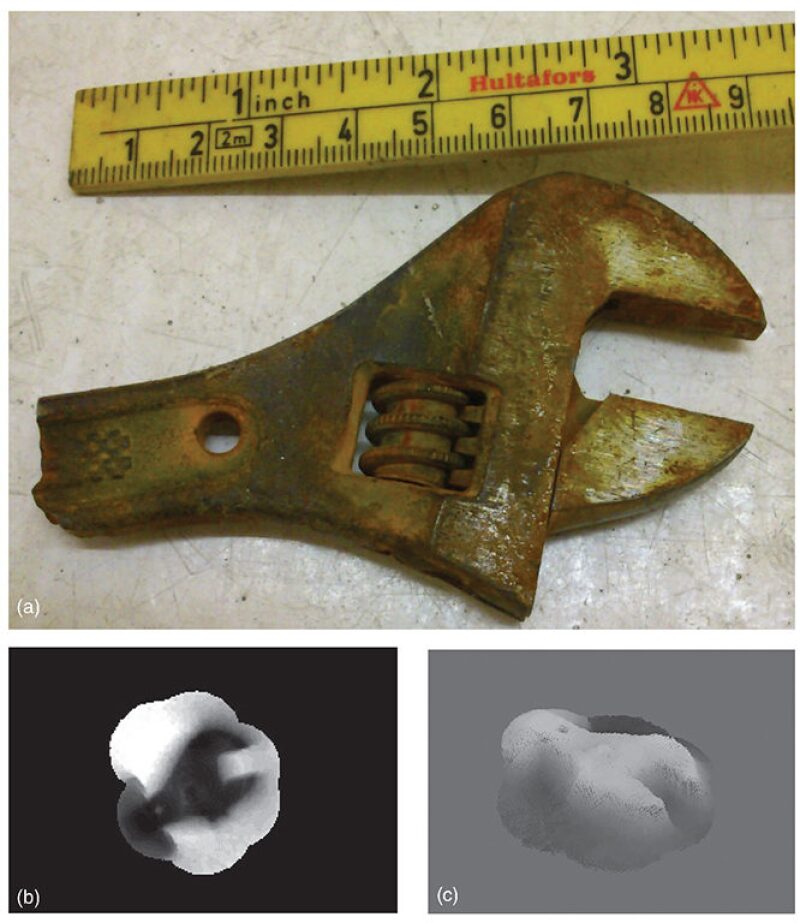
Fig. 2 above show a typical result obtained with an adjustable wrench placed in water over a span of 3.5 cm from the tool tip. The figures show a wrench, a 2D depth map, and a 3D visualization, respectively. The results were smoothed and filtered to reduce the effects of noise in raw data, and all the key features of the wrench were visible and identifiable.
In the 2D image, the adjustment screw and hole in the neck of the wrench can be seen, appearing as brighter spots on the dark object. In the 3D rendering, the topography of the adjustment screw is discernible, while the hole in the neck of the wrench shows up as a small divot. Overall, the laboratory testing revealed that the VR90 tool provides detailed and accurate images in a variety of fluids.
For the initial field testing, the tool was deployed in a deviated, cased-hole test well in Germany. Eleven separate runs were made to conduct tests and create images at depths of up to 2100 m (6,890 ft) and temperatures of up to 100°C (212°F). The goals were to verify the operational readiness and confirm the imaging capabilities in a range of target well environments. The tool performed well operationally and the fluid-based surface imaging technique provided reliable images of the test object.
For imaging, a steel test object in the shape of a starburst was attached to the bottom of the tool with a testing sleeve. Imaging was performed in the untreated well fluids without any special cleaning or preparation. The fluid was a mixture of water and traces of oil, with a large amount of suspended debris that included bits of rock, cement, and metal. Imaging tests were performed at a variety of depths and temperatures with accurate results obtained in real time.
In this case, the object could be unambiguously identified after only 90 seconds of imaging. After several minutes, millimeter-scale details became clear and the dimensions could be measured with high accuracy. In the final images, the outer diameter of the object was measured to within 3-mm accuracy, the width of the arms of the starburst to 0.5-mm accuracy, and the length of the arms to within 1-mm accuracy.
Summary
The innovative fluid-based surface imaging technique used in the VR90 wireline tool has been shown by laboratory and field testing to reliably provide dimensionally accurate visualizations of downhole equipment in real time. Based on X-ray backscattering principles, the technique works in both oil- and gas-filled wells, and even in dirty or debris-laden fluids.
Therefore, operators can forgo the time and expense of cleaning and preparing the well fluids for optical imaging, as well as the uncertainty with the use of ultrasonic imaging and impression blocks. As a result, well problems can be resolved in less time, saving rig hours and lowering costs.