A wide range of corrosive elements and compounds from a variety of crudes has led to a renewed industry focus on corrosion and the effects it has on pipelines and vessels. The additional attention has encouraged researchers to develop new techniques for mitigating the effects of corrosion and for monitoring the effectiveness of those agents.
The problem of corrosion is not new, but the production of additional crudes in recent years that would otherwise have stayed in the ground has led to higher concentrations of corrosive materials flowing through vessels and pipelines. Operators today face challenges from crude flows that have higher temperatures and pressures, more sand, and are more acidic. “These are causing really big issues. Twenty years ago, we just wouldn’t have been able to produce them economically,” said Cameron Mackenzie, senior scientist at LUX Assure. “The industry as a whole seems to be stepping up.”
The nature of the fluid that flows from the reservoir largely determines the corrosion monitoring and mitigation technologies. Reservoirs produce varying amounts of water, carbon dioxide (CO2), hydrogen sulfide (H2S), and other corrosive materials. Those characteristics can change from one reservoir to the next and can change from one segment of the reservoir to another. Further, the fluids from the reservoir can change over time as pressure falls and operators introduce water, all of which present challenges to engineers who design facilities to last the life of the reservoir, which itself is not known with certainty.
Internal corrosion of pipelines and vessels is a near universal problem that upstream operators face. The inability to manage corrosion can lead to metal losses, leaking vessels, lost production time, and unwanted cleanup costs.
Gokul Radhakrishnan, regional sales manager at MaxTube, said although there have been no recent breakthroughs in technology that stop all corrosion, there are some important evolutions and variations of existing technologies that allow operators to manage it more effectively. Corrosion management systems include installation of high-performance barriers and coatings, better understanding of chemicals and interferences, data acquisition and management, action protocols, models, verification, and some form of validation, he said.

In general, there are four strategies for managing corrosion. Operators can change the material every time it fails, replacing the tubing, surface lines, or even vessels when they fail. The second alternative is to change the material of construction to suit the processed fluids, usually by installing a corrosion-resistant alloy (CRA). Operators can also change the fluid by adding chemicals and inhibitors to make it less corrosive on the lowest cost material. Finally, an operator can install a barrier, such as a coating or lining, inside the pipe or vessel so that the fluid does not come into direct contact with the material, which is usually carbon steel, Radhakrishnan said.
Although most operators have a fairly comprehensive corrosion mitigation system in place, they occasionally lack the ability to link up financial costs of the choices made. “Any of the alternatives can appear the least or most expensive, so you have to do the life cycle costing,” he said. “Someone has to look at all these answers from the top and approve what works technically and economically,” Radhakrishnan said. Some operators focus primarily on the one-time first installation cost and do not look at long-term maintenance costs. In some of those cases, the operators would be better off spending more up front on capital expenditures and saving on operating costs over the life of the asset, he said.
To choose materials for corrosion-resistant surface facilities, Radhakrishnan said operators need to combine expertise from multiple disciplines not limited to facilities, such as geology, completion, drilling, reservoir, and the corrosion engineers. Many operators look at corrosion management and mitigation from a capital expense point of view. A better approach is to use a life cycle costing approach laid out in ISO 15663, he said.
Radhakrishnan said more expensive, and more corrosion-resistant, materials can save operators money if they are installed up front. In other cases, the opposite is true. They may be better off installing vessels and surface pipelines with cheaper materials. “For example, it may be OK to use the cheapest material when using it onshore as the onshore replacement costs are low. This may not be possible for offshore,” he said. In addition, operators must weigh carefully the life of the field when designing treating facilities and deciding on the corrosion strategy. “If the life of the field is, say about 5 years, why use a product that gives a life of 20 years, which may cost five times the money? A cheaper product which can do the work in 5 years may suffice,” he said.
A New Era
The uncertainty about the life of the field poses special challenges to engineers who need to manage corrosion. “We try to plan for the life of the field and don’t always do it very well. Some of the assumptions we make are based on sometimes scant data and some may never materialize. It’s typically a conservative guestimate, so you have to use whatever offset data is available and, ultimately, your experience,” said Eddie Stevenson, senior production chemist at Shell.
Flow from the reservoir frequently changes over time. “You may have sweet production at the start, but as soon as you start water injection, you may sour the reservoir,” he said. If the pipes are not equipped to handle the additional H2S, operating expenditures will rise. In many cases, the planning discussion is whether to spend more on capital expenditures up front to cope with the possibility of H2S production later in the reservoir life that may (or may not) occur, Stevenson said.
As operators move farther offshore, the higher temperatures and pressures of the reservoirs continue to stretch the limits of the existing technologies. Remotely operated vehicles, for example, have depth limitations and corrosion monitoring techniques that use these vehicles may not be applicable. “We cannot design for every feasible outcome, but the risks are much higher in these offshore developments and in the highly sour fields that are becoming more common,” Stevenson said.
“Because of the high pressure of these wells, the wall thickness of the pipe has increased significantly—increasing the weight of each joint and providing difficulties joining pieces of pipe together,” he said. One of the problems of high-pressure environments is that they accelerate the flow of production. When coupled with sand production, this can strip the protective inhibitor coating in tubing and present additional challenges to maintenance engineers, Stevenson said.
The deep water also provides extreme temperature profiles that pose additional problems for operators. The extreme depths of the US Gulf of Mexico reservoirs, and others, are posing challenges the industry has not faced. In the next 5 years, operators will have to figure out how to push a chemical inhibitor through a capillary tube 10,000 ft to the seafloor and another 20,000 ft (or more) to the reservoir.
The hot produced fluids rise internally while the chemical injection tubulars are bundled within the cooling seawater. At the base of this capillary tube is a check valve that needs to function with 100% reliability, Stevenson said. “We already know that we have functional problems with current injection valves at shallower depths,” he said.
This is more apparent in the batch treatment mode when scale inhibitors get injected into the line in surges and operators are unsure how much actually goes into the production flow. Stevenson said he expects the problem to be more severe at greater depths. “We’ve never done this before. We need very reliable check valves and process controls that prevent or minimize the surge effect with the injected chemicals, and we have little time to figure out how to do this as we are planning on first production some 5 years down the road,” he said.
The traditional material of choice for most pipelines and vessels is carbon steel. The higher the risks of corrosion, the more operators tend to focus on CRAs. The alloys are expensive and generally work well within a defined operating window, however, they have not been fully tested for the ultradeepwaters, Stevenson said.
Nonmetallic technology is an alternative in specific applications and has been used effectively in less severe environments. Shell has used internal coatings in pipelines and vessels with mixed success since the early 1990s. Glass-reinforced epoxy (GRE) pipelines are fairly common in water injection systems and some tophole casings have been run successfully in drilling operations. Researchers are looking into nanotechnology to make better coatings. “So in the future, we may have a more extensive variety of materials to select from for the specific project,” he said.
Chemical Inhibitors
Chemical inhibitors are widely used to minimize the rate of general corrosion and typically account for about half of the corrosion costs in the field. They can be applied in batch or continuously and require a network of infrastructure to transport, store, and apply them in an adequate dose, Mackenzie said.
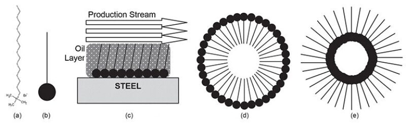
One of the most common classes of corrosion inhibitors are film-forming corrosion inhibitors, which form protective barriers on surfaces to prevent an attack from corrosive fluids. These corrosion inhibitors contain one or more active surfactants, which stick to surfaces and form a protective barrier against corrosion. The chemistry of these inhibitors varies, and some molecular structures are more effective than others in different physical and chemical environments. Some are more effective at restricting corrosion caused by CO2, while others are for corrosion from H2S. Some are oriented to high temperature, others do best in high salinity, while others have high erosion rates, Mackenzie said.
In many cases, corrosion inhibitors consist of a package of chemicals formulated to specific fluid properties of a given formation. These inhibitors react differently to temporal and spatial changes in conditions, such as temperature, pH, salinity, and solids in the fluid.
Often it is difficult to predict the optimal inhibitor when moving from the laboratory to the field. A dose that is too low allows a corrosive attack on the metallic vessels and pipelines and can cause long-term damage that ultimately leads to failure. Too much of a given inhibitor is expensive, because it incurs unnecessary costs of transportation, storage, and application and promotes the formation of oil/water emulsions, which need to be separated farther downstream, Mackenzie said.
The fluids can be sampled and analyzed for residual levels of active inhibitor components. The electrochemical and weight loss measurements indicate the effectiveness of a corrosion protection strategy at a specific point and measure corrosion that has already taken place. The sampling of a fluid is a labor-intensive approach, which requires expensive laboratory equipment. As a result, many operators look for a better method for judging the effectiveness of the company’s corrosion mitigation plan in the field, Mackenzie said.
The corrosion inhibitors in production (oil and condensate) systems are generally surfactants, soaplike substances that reduce surface tension. They can be applied in batches or in a continuous stream, depending on the circumstances of production. For many onshore wells, or in places where the chemical has to be trucked in, they are used in batches. In other cases, particularly offshore, where there are long lengths of pipeline that require pumping facilities, continuous injection works best. “Sometimes it depends on whether or not a pump can be installed,” he said.
A range of technologies can assess whether the operators apply enough surfactant to the production stream. The traditional approach is to measure the amount of specific chemicals downstream from their application. “We know how much goes in and we can measure for the presence downstream,” he said. Although sometimes adequate, this approach is often lacking in information because the application is generally a mixture of different chemicals and the tests do not measure for all of them. The operator does not get a complete picture of their application from the traditional tests, Mackenzie said.
In response, the industry has recently applied a newer approach. These surfactants tend to form micelles, agglomerated clumps of molecules, at the same time that they adequately coat the surface of the vessel or pipe they are protecting (Fig. 1).
About 5 years ago, the industry began testing the concentration of these micelles to measure whether the surfactant has an adequate dosage. An absence of these agglomerated clumps may suggest the dosage is insufficient, Mackenzie said.
Real-Time Monitoring
Corrosion monitoring equipment that monitors vessels and pipelines in real time allows operators to detect areas of corrosion more quickly and to take steps to mitigate its effects. Intelligent pipeline pigging allows operators to monitor internal corrosion more closely, particularly in environments in which standard monitoring techniques are not accessible, said Biji Poulose, United Arab Emirates operations manager of upstream chemicals at Baker Hughes.
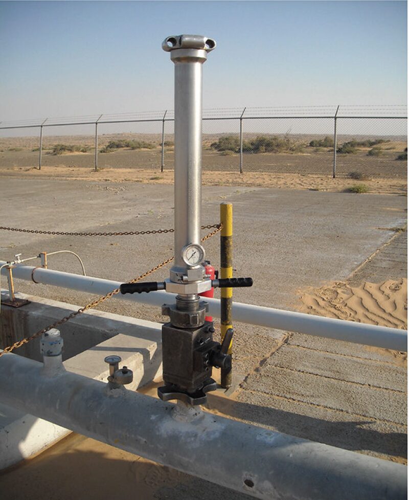
Traditional methods of monitoring corrosion include the use of metallic coupons (Fig. 2), fluid analysis, ultrasonic testing and radiography, which are generally more latent and time consuming than newer methods. Real-time monitoring techniques, such as strategically placed corrosion probes, enable operators to plan, deliver, and control appropriate mitigation methods. Engineers are careful to take into consideration the inclusion of these types of devices as part of corrosion mitigation strategies when they design the installations.
The industry has available a variety of software that can predict the potential effects of given fluid conditions and the corrosive effects they may have internally on pipelines and vessels. The software allows the designer to choose suitable materials and mitigation techniques, Poulose said.
“Corrosion mitigation has become more challenging as we move toward complex well completions and producing hydrocarbons from highly corrosive environments,” he said. More aggressive reservoir conditions, such as higher temperatures and pressures, higher concentrations of corrosive gases, and varying fluid conditions, have a huge effect on corrosion. As a result, operators may consider structured and systematic corrosion management systems to identify the risks and develop corrosion control measures.
In addition, an influx of H2S can lead to sulfide cracking of steel. The reaction of H2S with surface iron readily occurs and releases hydrogen onto the metal surface, which can easily penetrate the steel lattice, making it brittle. The brittleness of the steel can lead to the evolution of cracks, and thus, failure of equipment. This phenomenon is termed sulfide stress cracking or hydrogen-induced stress cracking. The detection of this type of corrosion is difficult because these cracks can form more quickly than in other types of corrosion. To avoid it, proper material selection or modeling to determine corrosion mitigation is important when designing the equipment.
“Reservoir souring is yet another problem we currently face,” Poulose said. In addition to the risk of corrosive environment, engineers need to be aware of the risk of bacteria buildup. Bacteria can be naturally present in the reservoir or it can enter the system through different mechanical interventions and sources of water. These sources can be injection water or any water sources used while drilling, or during well stimulation or well treatment. Bacteria grow rapidly if the food sources are available and the conditions are favorable for them. The presence of bacteria can lead to microbiologically induced corrosion. This is mainly controlled by treating the system with biocides or by treating the water before it is introduced into the reservoir, Poulose said.
To mitigate corrosion, many operators are turning to CRA. Operators can choose material with varying percentages of chrome alloys, based on the corrosivity of fluids and operating parameters. Commonly used CRA materials are 13Cr (martensitic stainless steel), alloy 316 (austenitic stainless steel), and 22Cr (duplex stainless steel).
Many chrome alloys are available with varying tolerances to temperature, pressure, and the presence of gases, Poulose said. However, the choice of material has to be decided carefully and should take into account well fluid changes over the life of the production, which often leads to the need to overrate the CRA and, hence, increase the cost and material lead time.
Stainless steel is often considered as being more resistant to corrosion; however, this is not the case in all sour or high chloride applications. Carbon steel is less expensive, requires tighter monitoring, and has more associated costs in terms of maintenance and chemical treatment. Operators also use nonmetallic piping and linings, such as GRE materials, for some specific known corrosive applications in which the temperature and operating pressures are low. These reinforced nonmetallic pipelines are resistant to corrosion, lightweight, easy to install, and less expensive, but they are more fragile than their metal counterparts, Poulose said.
Remote Monitoring
Alyn Jenkins, principal integrity management specialist at M-I SWACO, said operators are turning to monitoring systems that allow for real-time monitoring of facilities. Although the weight loss coupon remains one of the principal corrosion monitoring tools, operators are increasingly turning to linear polarization resistance and electrical resistance probes to monitor the corrosion remotely.
The monitoring probes measure the corrosion rate that is transferred to a data collection unit, and the data are then transmitted to an end user. “Using appropriate software, the operator can review this information in real time from his/her desk without visiting the field,” he said. The probes can be installed on surface pipelines or vessels to monitor the amount of corrosion that has occurred in recent history.
Nonremote corrosion monitoring probes require a trip to the field either to download the corrosion data or install and remove the weight loss coupons that also need to be analyzed in a laboratory. The data taken from coupons show the corrosion that has occurred over the previous few months, Jenkins said. “With real-time monitoring, you know minute by minute what is happening,” he said. If the corrosion rate of a given pipeline or vessel passes a given threshold, the user can set an alarm in the desktop software and take corrective action before the equipment suffers extensive damage. “If an alarm trips, you can make appropriate changes to mitigate the problem,” Jenkins said. Operators generally measure corrosion rate in mm/yr and become concerned when the corrosion rate exceeds from 0.05 mm/yr to 0.1 mm/yr.
Although the real-time information gives operators precise data, it comes at a price. The cost of each probe and the supplementary equipment (data collection unit and transmitter) required is far greater than the cost of a weight loss coupon.
Under deposit corrosion (UDC), which occurs underneath the sediment that may build up inside a pipeline, concerns operators of reservoirs with sand and sediment production. It is difficult to prevent with inhibitors because they may not penetrate the sediment at the bottom of the pipe. Inhibitors are absorbed by the solids, reducing the amount of chemical available to prevent corrosion. Therefore, higher than normal inhibitor dose rates are required to mitigate UDC. Operators use pigs to clean out the pipeline or additional chemicals are added to the system to remove the solids to prevent UDC.
Another challenge for engineers who manage corrosion is the ongoing evolution of environmental regulations. Norway, The Netherlands, Denmark, and the United Kingdom have regulations that affect production chemicals used offshore. In general, the industry has kept pace with the newer regulations by developing environmentally acceptable chemicals that also inhibit corrosion, Jenkins said.
Operators and service companies are challenged by the extreme temperatures from the deeper and hotter reservoirs. Reservoirs can reach temperatures in excess of 150°C, which may fall beyond the performance envelope of environmentally acceptable chemicals, he said.
Case Study
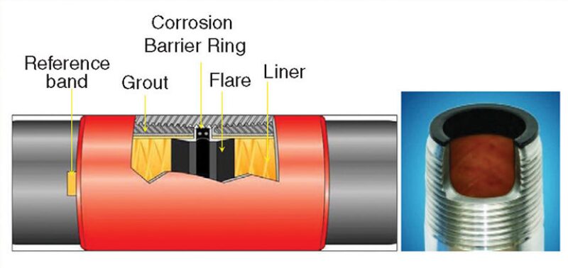
Saudi Aramco had corrosion problems in production tubing in one of its offshore fields, which was caused by the presence of H2S and CO2 and varying levels of water from the reservoir. In 2002, the company began lining its carbon steel tubing with glass reinforced epoxy (GRE) in three test wells. The strategy was to provide a barrier protecting the steel tubing from internal corrosion. A subcontractor inserted the fiberglass lining and cemented it into place. Saudi Aramco tested the tubes about 7 years after the installation of the lining and found that it was in good condition, which indicated the steel tubing remained protected from corrosion.
Based on successful trial test results, Saudi Aramco has used the technology to protect tubing strings in oil producing wells, water injection wells, water supply, and disposal wells. The GRE lining has better mechanical wear and resistance properties than plastic or epoxy coatings. The technique extended the well life and reduced workover operations stemming from corrosion-related problems. The operator has installed tubing with fiberglass lining in more than 50 wells between 2008 and 2012. So far, none of them have reported any failures.
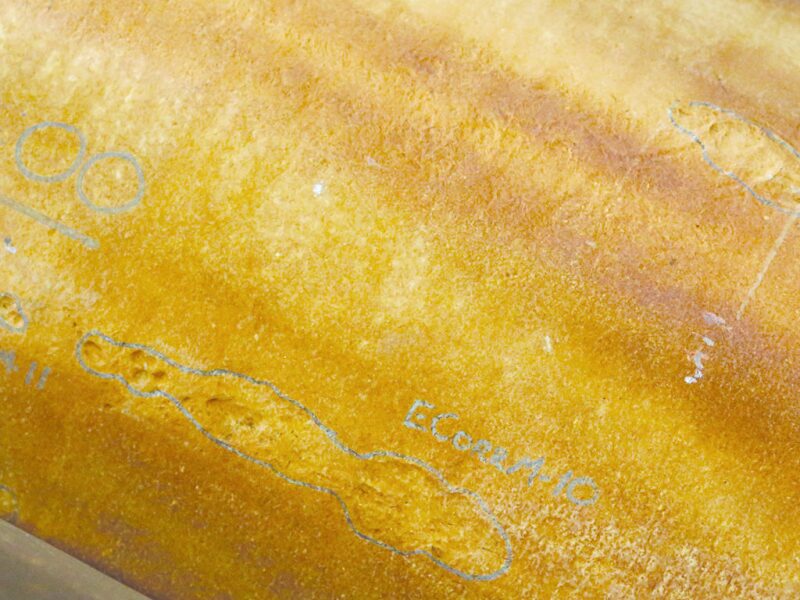
Although promising, the GRE has drawbacks. First, the technique reduces the inner diameter of the tubing and requires reduction in the sizes of production logging tools. Hydrofluoric acid, a common ingredient in drilling mud, cannot be pumped through GRE-lined tubing. Finally, GRE cannot be used on welded pipelines, which eliminates its use in most surface pipelines. In a few cases, however, some companies have applied it in onshore desert fields for oil gathering lines.
For Further Reading
SPE 130285 Potential for Measurement of Corrosion-Inhibitor-Micelle Presence as an Indicator of Optimum Dose by C. Mackenzie, LUX Assure, et al.
SPE 160236 Experience with Fiberglass (GRE)-Lined Carbon Steel Tubular for Corrosion Protection for Oil Production Applications by Q. Sharif, Saudi Aramco, et al.
SPE 164056 Inorganic Scaling and Chemical Inhibition Challenges Associated with Production of Reservoir Equilibrated Spent Acid Stimulation Fluids by T. Morrow, ExxonMobil Upstream Research, et al.
SPE 164097 Simultaneous Well Stimulation and Scale Squeeze Treatments in Carbonate Reservoirs by M.M. Jordan, Nalco.