The full-field development plan for the Khazzan project in Oman is based on drilling approximately 300 wells targeting gas-producing horizons at measured depths of approximately 6000 m with 1000‑m horizontal sections. The first attempt to drill these wells had to overcome many drilling challenges, including wellbore instability and drilling dysfunctions. This paper shows how the application of existing technologies and processes is leading to performance gains and improvements in wellbore quality.
Introduction
BP has embarked on an appraisal drilling campaign that targets a tight gas reservoir in northern Oman. The subject field is an area of approximately 2800 km2 and contains the Cambrian Barik, Miqrat, and Amin reservoirs.
The field-development plan is based on a deep-horizontal-well design. When the appraisal phase began, there was very limited experience within the country in drilling deep horizontal gas wells. Other operators in Oman were mostly drilling vertical gas wells. There were no analog data available on horizontal wells in the Barik reservoir.
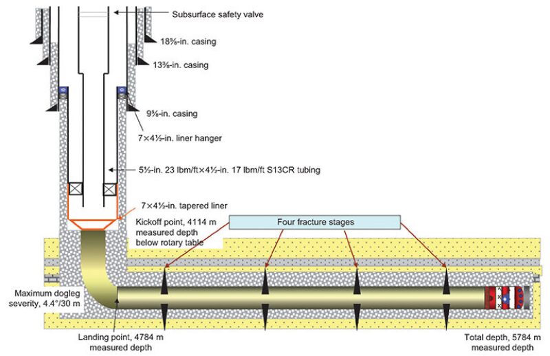
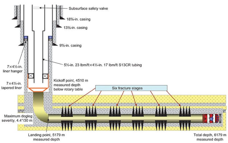
The wells will be drilled vertically to approximately 4000-m measured depth before building up and landing to horizontal in the Barik or Amin reservoir. An 8½×8⅜-in. 1000-m horizontal interval is drilled, and a 7×4½-in. tapered liner is cemented in place before fracturing operations. Fig. 1 above and Fig. 2 are schematics of the well designs.
The targeted reservoir is either Barik or Amin sandstone, both of which have a high unconfined compressive strength (exceeding 35,000 psi). The Barik sandstone is at the upper margins of the global rock-strength envelope. Indeed, when core samples were analyzed by the bit manufacturer, the strength far exceeded any of their global stock of reference rock samples.
Horizontal drilling in these hard-rock conditions presents several challenges:
- Hard rock and slow rate of penetration (ROP)
- High levels of shock and vibration
- Polycrystalline-diamond-compact (PDC) -bit cutter durability
- Drillpipe fatigue
- Wellbore stability
- Torque and drag management
- High downhole static temperatures up to 143°C
Challenges to Project Delivery
The 12¼- and 8½-in. hole sections consume more than 80% of the total drilling time; therefore, improving the ROP and bit-run longevity would have clear benefits for project economics. A hard-rock drilling strategy was developed. This strategy targeted drilling practices and procedures; optimization of bottomhole-assembly (BHA) design; usage of logging-while-drilling tools, including downhole weight on bit (WOB), downhole torque measurement, and pressure-while-drilling measurement; and selection of downhole tools.
A core aspect of the strategy is to increase the power available at the bit. The application of high-torque motors and the latest generation of drilling turbines, coupled with an improved understanding of downhole drilling dynamics, promotes the efficient transfer of energy from the topdrive to the bit face.
Several drilling dysfunctions were experienced in the first horizontal well, and it was recognized that, by addressing each of these issues, hole quality and drilling dynamics could be improved. A greater efficiency in transferring power to the bit, therefore, could be achieved.
Mud Weight. Once it was confirmed that the first well was suffering from borehole-stability problems, the mud weight was increased from a specific gravity of 1.31 to 1.39. This helped minimize wellbore breakouts that were a result of redistribution of the borehole stresses caused by hole deviation in those formations. The elevated mud weight was maintained to the well total depth and was applied to the second well with positive results.
Equivalent Circulating Density (ECD). Managing the ECD helps maintain the mud weight within a safe window. Therefore, it is one of the measurements that should be monitored continuously with a downhole pressure-while-drilling tool.
Time Dependency. The wellbore in the build section was deteriorating over time. This issue has been observed only on horizontal wells; no wellbore deterioration was observed on vertical wells.
Both Barakat and Mabrouk formations have high clay contents, which may react with water and swell. To examine the chemical reactiveness of these formations, the operator undertook a series of detailed laboratory tests on samples. This revealed that shales in this location are relatively inactive; therefore, chemical deterioration was deemed to be only a minor contributor to borehole degradation.
The instability is believed to be related to tectonic stresses combined with weak laminated clays, which will tend to collapse when disturbed by drilling activities.
Hard Reaming. The wellbore quality deteriorated after extensive hard reaming. The wireline-caliper log confirmed that the borehole enlargement was more severe where hard reaming had been implemented. Both Barakat and Mabrouk formations have laminated weak bedding planes, which break out because of harsh drillstring vibration.
Once the deteriorated wellbore condition was understood, a rotary-steerable system was introduced. This provided a smoother buildup, with improved weight transfer to the bit and less detrimental shock and vibration energy being imparted to the wellbore.
Torque and Drag Management. The deep-kickoff well design, coupled with high WOB requirements, leads to a risk of pipe buckling around the kickoff point. This limits weight transfer and can increase the risk of drillstring failure. Heavyweight drillpipe is spaced across this interval to reduce the risk of buckling and improve transfer of weight and torque to the bit.
Torque levels were approaching string limitations by the end of the first horizontal well. This situation resulted partly from earlier problems stemming from a mechanical sidetrack. High side forces were evident as the drillstring passed across the sidetrack interval. Friction factors were analyzed as drilling progressed through the abrasive-sandstone interval, and the torque projections were updated continually. Where possible, steering intervals were minimized to reduce wellbore tortuosity, although there were tight directional constraints to be maintained. Torque was also reduced by enhancing hole-cleaning practices. It was observed that on-bottom and off-bottom torque will drop after performing a cleanout cycle in the horizontal hole.
Hole Quality and Borehole Spiraling. In the problematic build section of the first horizontal well, the caliper log revealed that an increasingly severe spiraling pattern was present in the wellbore. This had been initiated while drilling with a rotary BHA in the vertical zone, and it continued with the turbine drilling assembly. Ultimately, a stiff rotary BHA with multiple roller reamers was required to clear the worst of the undulations and enable drilling to continue.
The spiraling signatures in the vertical part of the first well were mainly associated with excessive stabilizer spacing, short bit-gauge length, and poor wellbore condition. The stabilizer interval provided a self-perpetuating spiral pattern; each stabilizer followed the repeated undulations in the wellbore and caused the bit to continue the spiral pattern. The overgauged hole reduced the effectiveness of the stabilizers and allowed off-center rotation to be established.
Dynamic and static BHA analysis was made to predict BHA behavior. A variety of BHA designs were modeled with a long-gauge PDC bit. The results showed that the optimum BHA for maintaining low side forces at the bit was a point-the-bit rotary-steerable system coupled with a low-speed, high-torque motor. Another purpose of running a high-torque, low-speed motor was to deliver the power to the bit from a downhole drive system instead of from the topdrive, hence reducing the surface torque and wasted energy caused by drillstring and BHA dysfunctions. The low-speed aspect of the motor was to aid bit durability when drilling the abrasive formation.
Hole Cleaning. Drilling the horizontal sections through hard rock at a slow ROP should not, in itself, lead to a hole-cleaning problem. The turbines that are used in the horizontal section generate fines as opposed to PDC-bit cuttings, and these fines should be easier to remove from the wellbore. The ROPs are so low that the system should see minimal solids loading.
However, under certain circumstances, hole cleaning can become an issue even under these slow hard-rock conditions. In Well 1, wellbore instability resulted in increased solids loading in the wellbore, coupled with overgauged hole and the associated reduction in annular velocities. The flow rate was also restricted because of high turbine pressure losses. Having a turbine BHA with a bend limited the surface revolutions-per-minute value for optimum hole cleaning. Under these conditions, several instances of packoffs were experienced, which, in turn, contributed to further wellbore degradation.
In the next well, a rotary-steerable system was run in the build section, which helped increase the cuttings-carrying capacity, although it was still necessary to drill with turbines and diamond-impregnated bits through the horizontal reservoir. High-angle hole-cleaning practices were implemented, contributing to improved hole quality.
Shock and Vibration. Shock and vibration and stick/slip are common issues in hard-rock drilling operations. There is very little dampening of shocks because of the hard-formation/BHA interface, leading to greater severity and increased frequency of shocks. High WOB is typically required, especially in PDC-bit drilling, which contributes to increased levels of stick/slip.
The most severe shock and vibration were experienced in the first well through the build section. This resulted in reduced ROP and bit life and in BHA and drillstring failures.
The oversized borehole in the first well had a major effect on increasing the shock and vibration in the drillstring by increasing the lateral freedom of the BHA. Further adjustments were clearly required to improve dynamics. Dynamic simulation resulted in the recommendation to use a combined rotary-steerable system and a high-torque, low-speed motor as the most stable BHA to drill the vertical and the build sections.
Bit Wear. The horizontal reservoir section is hard and abrasive with occasional interbedded clays, to the extent that these formations are not yet considered PDC-bit drillable. This interval is, therefore, drilled with diamond-impregnated bits and turbines. The analysis from the second well showed more than 30% of the average bit-run time had been spent on tripping, so bit durability is a key to performance improvement.
A high-speed turbine improved the ROP by more than 25%, but the average bit-run length was less than 160 m. Diamond-impregnated bits require optimized WOB not only to maximize the ROP but also to extend the bit life. It has been found that running higher WOB increased the ROP to some extent but reduced the bit life substantially.
Downhole-Tool Reliability. There were several downhole-tool or drillstring failures in both wells, which required extra prevention or mitigation to extend the tools’ reliability. To mitigate these failures, the inspection program has been revised for all drillstring components. This involved following the highest service level for directional-drilling tools and applying the most rigorous inspection procedure for drillpipe and heavyweight drillpipe. A corrosion-monitoring program was put in place to monitor corrosion levels from the water-based drilling fluid and provide prompt mitigation with corrosion inhibitors as necessary.
Directional Control. In the first well, steering the well path within the tight tolerances of the directional plan was challenging and, in some cases, resulted in tripping out of hole for a correction run.
In the vertical part of the first well, stabilizer spacing was too long, which allowed the BHA to deviate from vertical. Reducing the stabilizer spacing and running a vertical rotary-steerable system helped eliminate drifting the well from vertical and minimized spiraling.
Results and Additional Performance Improvement
The first horizontal well had experienced multiple nonproductive-time events, and, ultimately, the reservoir section had to be sidetracked before finally achieving the required 1000-m horizontal interval in Hole 2.
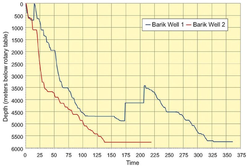
Application of lessons learned in the first well enabled construction time for the second well to be reduced by 53% and cost to be lowered by more than 30% (Fig. 3).
This article, written by Special Publications Editor Adam Wilson, contains highlights of paper SPE 166699, “Achieving Drilling-Performance Improvement in Horizontal Tight-Gasfield Development,” by Mohamed Najwani, SPE, Yaseen Najwani, SPE, and Hani Al Lawati, BP Exploration (Epsilon); Colin Cockburn, SPE, BP Exploration Operating Company; and Mohammad Reza Heidari, SPE, and Martin Sanderson, SPE, Schlumberger, prepared for the 2013 SPE/IADC Middle East Drilling Technology Conference and Exhibition, Dubai, 7–9 October. The paper has not been peer reviewed.