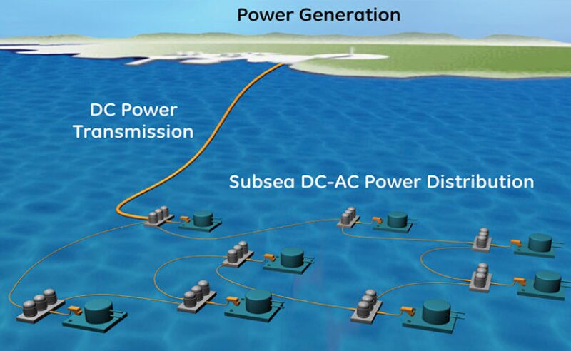
The vision of installing large subsea production facilities in remote offshore locations is today, simply not feasible. The problem is that subsea power systems are not designed to transmit high-voltage electricity to a production facility or pipeline tieback that may be under thousands of feet of water and 100 miles away from the nearest power plant.
Today’s subsea power-distribution technology is largely based on alternating-current (AC) technology, which, because of its electrical characteristics, can only be efficiently transmitted across a distance of 90 miles. In most cases, however, the effective distance is much less. On average, subsea tiebacks receive power from a platform or vessel located not more than 10 miles away and, in the case of most subsea processing systems, even closer. In an AC-supplied system, the flow of electricity alternates back and forth across the transmission line and is the form of electricity most commonly used in homes and businesses around the world. When long distances are involved, AC power distribution becomes a complicated operation and requires a great amount of attention to detail because of the physics involved with voltage regulation.
The search for an alternative to conventional AC systems has revealed the need for multiple technological advancements, from pressure compensated electrical switches to highly-conductive cables able to deliver power more efficiently. About 5 years ago, “We were looking at going to farther distances with alternating current instead of direct current (DC) because most of the equipment we have right now is AC powered,” said James Pappas, vice president of the Research Partnership to Secure Energy for America’s (RPSEA) ultradeepwater program.
He said that, after studying the issue, however, it was determined that using AC power could result in a 35% power loss in a 100-mile-long cable because of resistivity and other factors. Not long after that conclusion was reached, General Electric (GE) approached RPSEA with a concept to transfer all the power to a deepwater field with DC and then use a subsea transformer module located within the field to convert some of the power to AC. With this system, the expected power loss over 100 miles could be as low as 25%. “So, if you have AC components, it can convert power to AC for those components, and if you need DC, then it has DC components,” Pappas said. “It all sounds pretty simple until you want to put it in a package and then set it down in 10,000 ft of salt water.”
To prove the concept, RPSEA and GE began a 4-year-long project in 2009 to develop the best method of transmitting DC electricity from an onshore or platform-based power plant to a deepwater field located 100 to 160 miles away. A DC solution has the potential to eliminate some of the issues technology developers are expecting to encounter in long-distance AC systems. One of the challenges involved with AC is that, as the positive and negative electrons move back and forth across a power cable, they generate an electromagnetic field. This can lead to malfunctions in electrically controlled rotating equipment, such as compressors. In contrast, the electrons in a DC cable move in the same direction, which eliminates the risk of creating an electromagnetic field.
The simulated deepwater field used in the project was a four-well cluster supported by a number of all-electric subsea components including downhole pumps, seabed pumps, trees, compressors, and a chemical-injection system. “Then, we needed to think about all the controls that go to the well, to the manifold, and to each one of those components,” Pappas said, noting that the power demands for such a system could surpass 80 MW. “A few years down the road, if we have separation, we may be looking at reinjecting water into disposal wells or even seabed disposal if we can reliably get the water clean enough.”
RPSEA and GE’s USD-5.8-million project concluded in November and resulted in engineering drawings and working mockup units that they believe can be scaled-up. RPSEA now wants to move forward with a full-scale prototype system that can be tested in a subsea environment.
Technology Gaps
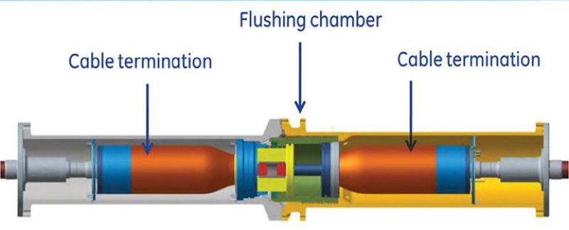
The RPSEA and GE project answered many questions, but it also identified technology gaps that must be addressed. Among them is the lack of a proven subsea DC connector, which is needed to provide a reliable connection from a power cable into subsea machines. “One of the things we recognize is that we don’t have enough information on how connector technology works in that subsea environment,” he said. “So we don’t know what we don’t know.”
Because they are exposed to the environment, subsea connections are more vulnerable than the internal components of a subsea system and, in many cases, are the first pieces of critical equipment to fail. To overcome the lack of a reliable solution, RPSEA recently solicited bids to develop a prototype of a subsea connector that can handle high voltages and high pressure.
The project’s deliverables include designing a DC wet-mate and dry-mate connector for performance and durability testing. Pappas said that, because of the complexity of what the project is trying to achieve, the DC systems under development are nothing like what has been designed thus far for onshore or subsea applications.
Another issue yet to be resolved is how to protect a subsea system from power spikes that can occur during transient conditions such as a startup, shutdown, or an electrical fault. If not managed properly, an electrical spike can resonate through the entire system until burning out a component at the end of the line. The large number of electrical systems a spike could flow through inside a complex subsea processing system only adds to the likelihood of a failure.
To counter the risk of overloading the electrical system, engineers must develop technologies that can detect and isolate faults and shutdown the subsea system if warranted in time to avoid damage from a power surge. However, not everything in a subsea system can be turned off immediately, such as a compressor, which needs time to dissipate its internal pressure before a safe shutdown is achievable. “It goes beyond the electrical components themselves,” Pappas said. “You have to have the smarts installed so that the system knows exactly what to do in any type of situation you can envision.”
Fault Detection
The amount of time and money involved with bringing a subsea power module to the surface for repairs or maintenance increases the need for simpler, more durable designs. In some cases, companies will be able to endure isolated faults on a temporary basis without shutting in production. In other cases, a major fault or a series of faults could force a total shut in of production.
According to Terence Hazel, a senior engineer at Schneider Electric who has worked on subsea power solutions and written numerous papers on the subject, faults in electrical equipment are almost certain to occur, but the trick is to know where. “If you know what has to be replaced, you put the replacement module on the boat, retrieve the faulty module and install the new one,” he said. “If you don’t know exactly what module is the one that failed, then it could be all for nothing and when you try to reenergize (the power system) you will have the same problem.”
Rather than add sensors to the system to tell operators where the fault is, a simpler solution may be to use a remotely operated vehicle to place plugs onto the system’s external electrical connections and run tests to determine where the fault is located.
To keep it simple and improve the availability of parts, Hazel said developers of next-generation subsea power distribution systems are trying to use as few mechanisms as possible. “Every time we have to put something else in, you end up creating a lot more potential problems that could outweigh any possible advantage,” he said.
Pressure Compensation
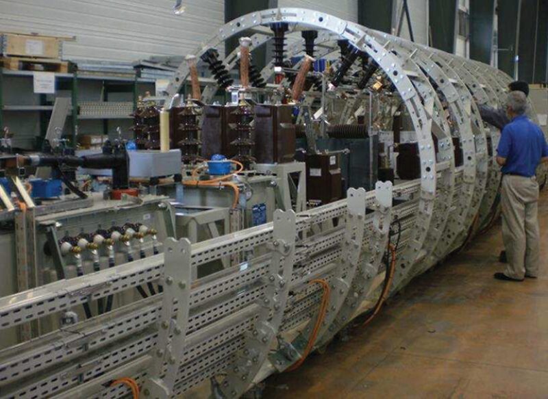
While there are drawbacks, AC is still the preferred power solution for most subsea projects and developers are looking for more ways to better enable long-distance AC systems using current technology. One of the more promising developments in AC distribution is the Ormen Lange subsea gas compression pilot project underway in Nyhamna, Norway.
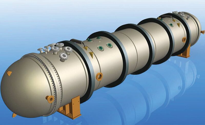
The pilot system is in a 45-ft deep tank where it is being tested to verify various subsea technologies, including the AC distribution system Schneider Electric designed and built inside the subsea switchgear module. Schneider’s system is using proven technologies to distribute power to the subsea compression station. Upon completion of the pilot operation, the system will be reinstalled in the Ormen Lange field, 78 miles from its power source and at a depth of 2,950 ft.
To prevent corrosion, normal air was removed from the switchgear module’s pressure vessel and replaced with dry nitrogen gas, which provides an oxygen-free environment. For depths even deeper than Ormen Lange, Hazel believes that the absence of high-voltage switchgears capable of withstanding ultra-deepwater pressures will push companies into building stronger enclosures for power systems. “The downside of using that technology is that you have a higher risk of leaks,” he said.
A potential, and theoretically more attractive, alternative to using pressure vessels could be to use pressure compensated equipment instead, which are typically filled with oil. The problem with that concept is that no one has figured out how to do it with subsea switchgears. “Either you make a very reliable pressure enclosure, or you find someone who can design a circuit breaker that can work in a high pressure oil filled environment,” Hazel said. “The oil majors would be very keen on somebody coming up with that idea.”
However, Hazel added that the development of such a technology would have such marginal applications that it could be too costly to develop. And whether gas filled or oil filled, the switch gears and other electrical systems must be proven to be extremely reliable for subsea use.
Nanotube Power Cables
In a separate but related subsea power project, RPSEA subcontracted NanoRidge Materials, a company that specializes in developing nanomaterial-enabled products, to develop a prototype of an ultrahigh-conductivity umbilical cable using carbon nanotubes as the conductive element. Originally conceived as a lightweight power solution for aircraft, carbon nanotubes have the potential to become an enabling subsea technology.
Carbon nanotubes are a single atomic layer of graphene rolled into a seamless cylinder many times stronger than steel. If compared to a copper cable of the same length and diameter, a carbon nanotube cable would be only a sixth of the weight, which means smaller and less-expensive vessels could be used to transport and install subsea power cables. “Oil and gas companies have been clamoring for a lighter cable for quite some time, and they see many applications for carbon nanotubes,” said Chris Dyke, a senior chemist at NanoRidge. “Some people are looking at this technology from a strength perspective, and others see it from a lighter-weight conductor perspective.”
According to RPSEA, a major driver behind the development of carbon nanotubes is that they have the potential to reduce power losses by up to 90% over long distances when compared with AC systems using copper. Delivering high-voltage electricity down a subsea cable with enough capacity to power a subsea facility at distances approaching 100 miles is not an option using copper, but that may someday be possible with nanotubes. As electricity flows through a copper wire, it builds resistance counter to the direction of energy flow, which raises the temperature and correspondingly lowers the wire’s ability to conduct electricity. Dyke said this phenomenon is known as the skin effect, where the current density is greatest near the surface and diminishes further into the conductor. “If the mechanism of carbon nanotube conductivity is channelization through many 1-nm-in-diameter conductors and we diminish or entirely overcome the skin effect, then the carbon nanotube wire can be 35 to 50% smaller in the diameter with the same power rating,” he said. Or, he added, “We can make the same diameter conductor used in current umbilicals but with decreased resistance at higher frequencies, essentially putting more power down the line.”
NanoRidge initially focused on purchasing nanotube materials and extracting fibers using a polymer agent. The company found that the extracted material was a poor conductor of electricity and that it would be more feasible to produce the nanotubes themselves into the desired diameters. Now in the second year of the umbilical program, NanoRidge is yielding positive results in terms of achieving conductive parity with copper but isn’t quite there yet. “We’re at a point now where we are getting 10−5 Ω·cm resistivity, where the copper is 10−6,” Dyke said. “The goal is to get to 10−6.”
As described in a technical report by Nanoridge, to make the nanotube wire, the company uses a custom-built tube-shaped furnace arranged vertically so the end product can be drawn out of the top. A liquid carbon source, mixed with a set of chemical additives, is fed into the furnace, where it undergoes thermodynamic and chemical processes that transform the liquid into a black elastic gel, or aerogel. Inside the furnace, the aerogel is then consolidated into fibers and spun out in the form of a bare conductive cable that is wound onto a spooling system. The take-up velocity is synced to the liquid feed rate so that the product can be spooled up as it is being formed. “The idea is that this is a continuous process where we can make miles of material in a single production run,” Dyke said.
From there, a polymer jacketing material routinely used on conventional copper wire is applied as a protective measure, after which the cable is ready for testing. In terms of cost, NanoRidge says that its technology compares very favorably with copper umbilicals but is less competitive against aluminum, which is also used in subsea power cables. In the second quarter of this year, NanoRidge plans to produce a mockup power cable and test it under 5,500 psi of pressure. After that, the next step is to produce a power umbilical capable of transmitting three levels of high-voltage electricity.
Because they are made of a nonmetallic substance, carbon nanotubes are not susceptible to corrosion. Another advantage carbon nanotubes hold over copper is a longer fatigue life because of the material’s tensile strength. “If you look at the stress/strain curve of a carbon nanotube fiber, necking and strain hardening do not occur as with most metals,” Dyke said.
“Also, if you compare the tensile strength of carbon nanotube fibers and copper, 6 GPa and 0.22 GPa, respectively, the carbon nanotube fiber is considerably more tenacious than copper. This allows designers to potentially reduce armoring due to the higher top tension capability,” he said.
NanoRidge is also exploring the use of its nanotube cables for wireline and downhole monitoring operations. The company believes that the strength of the material and its high conductivity will allow companies to multitask, using a nanotube cable as a tool and a source of power.
For Further Reading
OTC 20468 Impact of Subsea Processing Power Distribution: Subsea Switchgear Module—A Key Enabling Component in Subsea Installations by Terence Hazel, Senior Member IEEE. et al.
OTC 25340 Ultrahigh Conductivity Umbilicals: Polymer Nanotube Umbilicals by C. Dyke and L.M. Jacobs, Nanoridge Materials, et al.