
A successful pilot test of polymer flooding was conducted in the San Jorge Gulf basin, a mature waterflood with the presence of heterogeneous reservoirs and viscous oil under reservoir conditions. During the past 5 years, 3,200 tons of hydrolyzed polyacrylamide polymer was injected at concentrations of 1,500 ppm. The polymer flooding resulted in an increase in oil production to 100% and a decrease in water production to 50% in original central wells.
Introduction
The Diadema oil field is in the San Jorge Gulf basin in southern Argentina. The field has 480 producer wells and 270 injector wells. The reservoir being polymer flooded is characterized by high permeability (an average of 500 md), high heterogeneity (10–5,000 md), high porosity (30%), very stratified sandstone layers (4–12 m of net thickness) with poor lateral continuity (fluvial origin), and 20 °API oil (100 cp under reservoir conditions).
Polymer-Flooding Pilot
The polymer-flooding pilot started in -October 2007 with five injectors and 19 producers. Four wells are called original central wells and are the producers that receive 100% of the polymer-solution injection. These are the most important wells for the project because their behavior will dictate the evolution of this technique for the possible expansion to other waterflooded areas of the field. The pilot was extended in 2009 when four injectors were converted from waterflood to polymer flood and again in 2011–12 when four more injectors were converted from waterflood to polymer flood. The pilot now has 13 injectors and 36 producers, 14 of which are central wells.
The injected-polymer-solution concentration is 1,500 ppm, reaching 15- to 20-cp injection viscosity. In some areas of the pilot, a higher concentration of polymer solution was tested (3,000 ppm), reaching 30- to 40-cp injection viscosity. Corefloods and screening of several polymers were conducted before the start of the pilot project.
Mobility-Ratio Improvement. During waterflooding, the endpoint mobility ratio was 80. With this very unfavorable mobility ratio, viscous fingers may appear, leading to severe channeling, especially when layers with different permeability are present. Also, early water breakthrough produces increasing water cut in producer wells. In addition, inefficiency in areal and vertical sweep will occur. By injecting a viscous polymer solution, the mobility ratio decreased to 5, still unfavorable but with better areal- and vertical-sweep efficiency than that from waterflooding. The average viscosity of the injected polymer solution was typically 15 to 20 cp. For this level of displacement-fluid viscosity, an increase in sweep efficiency in the fractional-flow curve translates to less injected fluid needed to achieve similar oil production.
Water-Cut Behavior. Before the start of the polymer-flooding pilot, with 1.5 pore volumes injected (PVI) of water, water cut reached 97.5% and recovery factor (RF) expected from secondary recovery was 12% (RF from primary recovery is 13%). In central wells, after 5 years and 0.8 PVI of polymer solution, water cut decreased to 83%.
In original central wells, the first response seen from 0.2 to 0.4 PVI was that water cut decreased only from 97.5 to 92.5%. A higher-concentration injection test (3,000 ppm) was started in the injectors surrounding original central wells, and water cut continued decreasing to 82.5%. Channeling problems started with the second expansion of the pilot (when injectors were tied together to share the same pump, thus unbalancing injection). These problems occurred at 0.55 PVI, and water cut rose to initial values. After several gel treatments and the use of curlers in injector wells, these channeling problems were partially resolved and water cut decreased to 80%.
Production Response. Oil production from the original central wells increased to 100%, and the average water/oil ratio (WOR) of central producers was 33 m3/m3 before the polymer flood. Six months after polymer injection started, a decrease in water production and an increase in oil production were seen in the original central producer wells and in some peripheral wells and WOR decreased to 5 m3/m3.
Learning Curve
The pilot has a high initial investment in facilities, a high direct labor cost, and significant polymer consumption. Additionally, several problems were presented during the past 5 years (e.g., channeling and unbalanced injection). These issues must be solved and optimized in order to plan a possible expansion of the technique to other areas.
Some of the techniques tested within the project area in order to solve some of the problems presented during pilot implementation are as follows:
- Gel treatments for depth profile modification to solve channeling problems between injector and producer wells
- Use of curlers to regulate injection between injector wells sharing the same pump
- Use of new progressing cavity-pump (PCP) system to mitigate wear problems and intervention rate in producer wells
- Use of concentrated solution to reduce energy consumption, taking advantage of system pressure and reducing the size of facilities
Gels. In order to improve flooding sweep efficiency by profile modification, gels were injected into polymer-injector wells during the last years of the project. Candidate wells have high-injectivity/high-permeability layers and poor vertical-sweep distribution. Gels are injected from the same polymer plant, adding crosslinker to the pump of the well to be treated and shutting off dilution water (to reach a polymer-gel concentration of 3,000–4,500 ppm). Chrome acetate is used as the crosslinker. As a result, vertical-sweep efficiency has improved in several wells.
Curlers. The expansion of the project from five to 13 injectors while using the same facilities has created injection-control problems. Two or three injectors had to share the same injection pump, so wells with the same (or nearly the same) wellhead injection pressure were tied together. Although the difference between pressure ranges from injectors was low, the injection started to lose balance. Some wells had more injectivity than others and took almost the entire polymer injection, leaving the others with no injection.
The use of conventional regulator valves was not an option because they produce severe shearing of polymer solution, diminishing injection viscosity (high pressure differentials in small lengths cause mechanical degradation). In order to mitigate the pressure differential between wells, curlers were tested in these wells with more injectivity (Fig. 1 above).
The length of the curlers (inner diameter is 0.5 in.) is designed for the polymer-solution viscosity pressure drop required to level the pressure differential between wells. A curler is added in line to the injector that has less injection pressure, thereby balancing injection. Shearing of the polymer is minimal, and multiple wells could be aided from one pump. Samples were taken before and after the curler was placed, to measure viscosity. No shearing of polymer solution was seen.
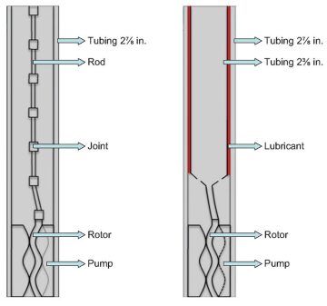
Lubricated Transmission System (LTS). The purpose of this development is to provide an arrangement for hydrocarbon extraction in wells equipped with PCPs. The aim is to reduce wear of the conventional tubing used in the extraction of fluids from friction and corrosion. It consists of a rotating tube inside the production tubing. Between the rotating tube and the production tubing, there is a space into which an antifriction lubricant is injected (Fig. 2). The bottom end of the rotating tube has a section with holes that allow fluids to flow into it. The section is connected to the PCP by a rod; its top end is connected to a production outlet and its propelling motor mechanism. The upper section of the fixed tube is connected to an antifriction-lubricant-injection pipe in the space left between the rotating tube and the fixed tube.
Concentrated Solution. At the beginning of the pilot, the authors sought to confirm viscosity development of the polymer solution injected. After several dilution tests, a decision was made to use concentrated solution and post-dilution with water to achieve a final injected-polymer-solution concentration of 1,500 ppm to optimize facilities used to produce and inject the solution and take advantage of water-injection-system pressure, saving energy. The pilot expansion from five to 13 polymer-injector wells demanded an increase in polymer-solution rate from 1000 to 2000 m3/d. Using the same facilities, polymer concentration was increased to 3,000 ppm and then diluted with injection water to obtain an injected-polymer-solution concentration of 1,500 ppm. This technique allowed using the same size of maturation tanks and pumps and uses existing-injection-system pressure.
Gel Treatments to Water Injectors Next to the Polymer Plant. To optimize the use of the polymer-injection facilities, diminish direct labor cost, and reduce treatment cost per well, gel treatments are conducted using current facilities. One pump is isolated to inject only concentrated solution with the crosslinker, and this feeds pipelines connected to water-injection satellites. Each injector is treated independently, and the treatment is controlled directly from the polymer plant. This allows increasing gel-treatment volume (between 20,000 and 40,000 bbl) per injector well and improves profile modification and volumetric-sweep efficiency.
Water Quality. The polymer plant is fed with production water treated at the South Treatment Plant in the field. This water (“S” water) is not the best for developing polymer-solution viscosity. It has 15,000 ppm of sodium chloride (NaCl) and 1,000 ppm of hardness as calcium carbonate (CaCO3). The North Treatment Plant in the north part of the field receives mostly production from primary- and secondary-recovery projects and has better production-water quality (“F” water)—12,500 ppm of NaCl and 500 ppm of hardness as CaCO3. Viscosity development of the polymer solution with this water is significant. Under current conditions, a viscosity increase of 44% has been obtained.
Before the pilot, several tests were conducted with the two types of water, and the viscosity difference was very low. At first sight, they did not seem to be very different; nevertheless, the viscosity development between them was found to be very different under field conditions. It was noticed that, when water samples were taken in situ and then sent to laboratories far away from the field, the aging of the samples produced changes in water properties and gave misleading results regarding viscosity development of the polymer solutions. The advantage to having an in-situ laboratory at the polymer plant and conducting all tests regarding water, polymers, and gels on site is that it prevents aging and changing of the properties of the water samples.
Several laboratory tests were made to determine the main viscosity killers, the chemical agents that degrade -polymer-solution viscosity. The presence of divalent cations, in this case represented by Ca2+ of calcium chloride, demonstrated a large effect on viscosity development. “F” water content of divalent cations is half that of “S” water, so this characteristic can mainly explain the better viscosity response with the former.
This article, written by Special Publications Editor Adam Wilson, contains highlights of paper SPE 166255, “Polymer-Flooding-Pilot Learning Curve: 5+ Years’ Experience To Reduce Cost Per Incremental Barrel of Oil,” by J. Buciak, SPE, G. Fondevila Sancet, and L. Del Pozo, Grupo CAPSA, prepared for the 2013 SPE Annual Technical Conference and Exhibition, New Orleans, 30 September–2 October. The paper has not been peer reviewed.