
Measurement-while-drilling (MWD) tools were introduced to the oil and gas industry in 1978 by what was then known as Teleco Oilfield Services (bought by Baker Hughes in 1992). Ever since, the industry has had to contend with designing computer circuit boards populated with electronic components that must perform reliably under a combination of extremely harsh downhole conditions. The primary hostile conditions are temperature, variable amounts of vibration, and intermittent shock. Additionally, designers must consider the limitations of the downhole batteries and alternators used to power the electronic assembly. This combination of conditions, in fact, is at least as demanding than those encountered in the defense, space, aeronautics, and automotive industries.
Electronic components include capacitors, resistors, inductors, transistors, oscillators, resonators, semiconductor chips, processors, and memory chips.
The bulk of the electronic component market serves commercial needs. “Even though it’s come a long way in the last 10 to 15 years,” said Matthew White, director of engineering at Ryan Directional Services, “still I would estimate that 85% of the integrated circuits [ICs] and parts on the market today are rated at 85ºC. And another 10% to 12% are rated to 125ºC. Maybe 2% or 3% are rated anything above that.”
With downhole temperatures routinely reaching 150ºC to 175ºC within the deep shale plays in the United States, and offshore downhole temperatures reaching as high as 200ºC, particularly in southeast Asia, the industry demand for reliable MWD and formation-evaluation-measurement-while-drilling (FEMWD, also known as logging-while-drilling or LWD) tools continues unabated. The problem is that the oil and gas industry’s demand for high-temperature electronic components is comparatively tiny—combined with defense, space, aeronautics, and automotive, estimated to be less than 1% of the total component market.
Additional splintering of demand results from individual oilfield services companies keeping exclusive agreements with component manufacturers secret. “I’m more of the opinion,” said Robert Estes, manager of emerging technology, Drilling & Evaluation at Baker Hughes, “that we have to encourage the development of components that can be shared between military, aerospace, automotive, oilfield operations, and geothermal.”
Aaron Schen, department manager of the Electronics Development Group (Downhole) at National Oilwell Varco (NOV), notes that, generally, non-semiconductor downhole components such as sensors and connectors are pretty well supported by vendors. “It is routine to find high-temperature, high-severity, and high-pressure (if needed) ratings for those types of components,” he said. He contends this is because a small, niche-market company “can be happy making a couple hundred pressure sensors a year. Chips are turned out in the millions.”
The economies of scale are such that it generally is not worthwhile for chip manufacturers to go to the trouble of engineering and assembling high-temperature components when an order might be as few as a hundred a year.
In addition, an emerging high-temperature component market like the automotive industry might make specific demands that are less onerous than those required by MWD tools while buying many more components than a typical oilfield service company would, thus keeping their costs low—and rendering the part useless for the oil field because it is not rugged enough. “Even selling a part for USD 5 as opposed to USD .40,” said Robert Warner, electrical engineer at NOV Downhole, “is not going to motivate a manufacturer to modify this part for your application because they’re not going to make any money in return.”
Downhole Computing
MWD/LWD tools consist of instrumentation packages that typically measure azimuth, inclination, temperature, pressure, gamma radiation, and oftentimes vibration and strain. They are located in the bottomhole assembly (BHA) so they can provide real-time, near-bit information used in navigating the drill bit such that it either hits or, with horizontal drilling, keeps within the pay formation and drills at a consistent angle, in a consistent direction, at a consistent depth. The real-time information can also help ensure that drilling is proceeding as quickly as possible yet within the overall assembly’s operating limits, without compromising the functioning of the BHA, while avoiding drilling a tortuous hole.
Transmission of the downhole data is typically achieved using pressure pulses of drilling mud that travel up to the surface. Pressure pulses are created by controlling a mud valve near the bit. The data rate is slow, at less than 10 bits per second. In contrast, the slowest Internet file upload, download, or transfer speed is 56 Kbps or 5,600 times faster than typical downhole telemetry. National Oilwell Varco offers its IntelliServ wired-pipe or networked drillstring telemetry that does have the capability to transmit data at a rate of 57 Kbps, but its use is not the norm.
“The most complicated BHA and the most expensive BHA—with rotary steering, formation evaluation, and more,” said Aaron Schen, “I’m sure doesn’t have as much processing power as a cell phone.”
However, the data generated by downhole computers are highly significant.
And, of course, a cell phone would likely not survive even the first 10 ft of drilling.
Protection from Pressure and Heat
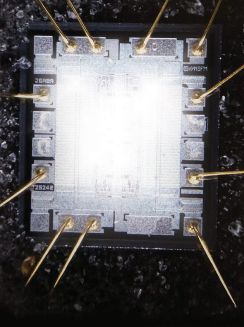
According to Halliburton patent number WO2010036244 A1, “Downhole hydrostatic pressures can reach 10,000 psi, and sometimes up to 20,000 psi or above. Therefore, it is well known that the sensitive electronics must be disposed in a pressure housing or vessel to shield the electronics from the downhole pressures, thereby avoiding damage. The pressure vessel also protects the electronics from corrosive and conductive fluids in the downhole environment. Such a pressure vessel may use O-ring seals coupled to a pressure housing, with Inconel [a nickel-base alloy with chromium and iron] used to maintain a rigid vessel and good seal surfaces while in a corrosive environment.”
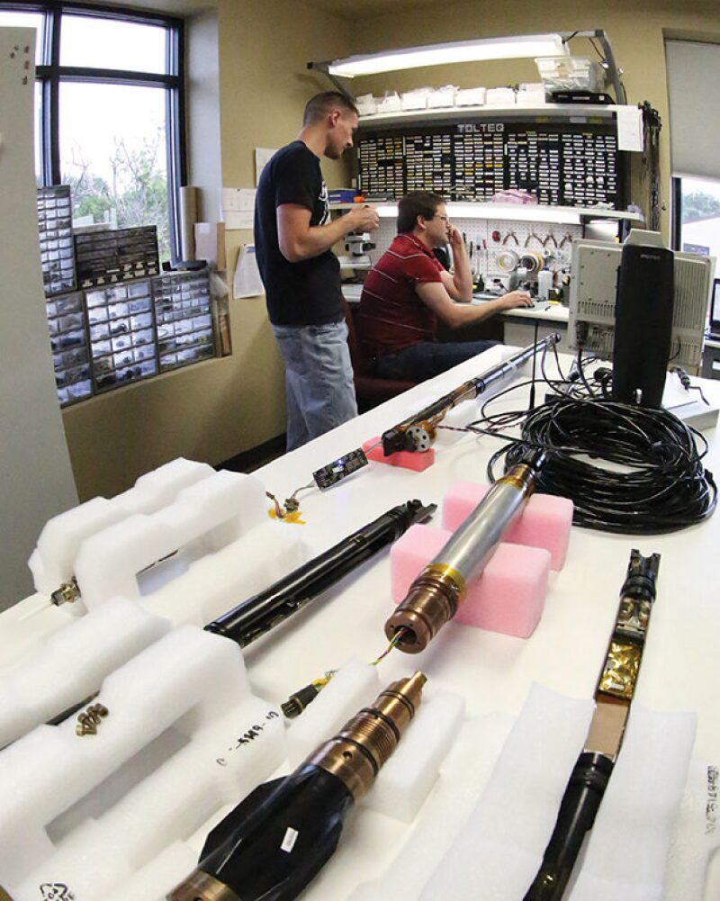
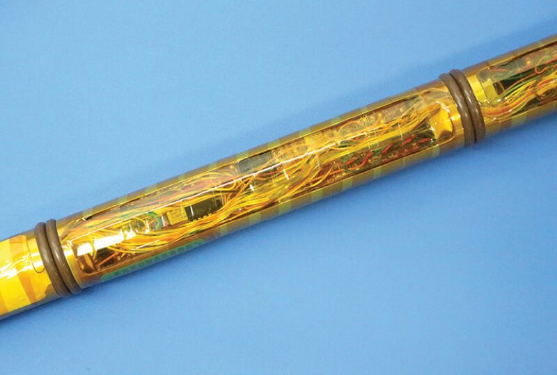
The pressure housing is called a probe or pressure barrel (or sonde when used with wireline tools). The pressure barrel is a “long, skinny metallic tube that sits around a chassis that holds all the electronics,” said Ryan’s Matthew White. “It’s like a gun barrel, made to resist pressure differentials.”
Batteries Heat Up, Too
According to independent service company Gyrodata, its Monitor MWD/survey-while-drilling tool consists of a shock-isolated directional sensor package and electronics section housed in a beryllium copper pressure barrel with a battery-powered rotary pulser unit. This would be similar to how other MWD/LWD electronics are housed in pressure barrels.
During drilling, the electronics are thereby held at atmospheric pressure while everything around them is seeing the extremes of the downhole pressure environment. “It’s like a submarine,” explained Schen. “A submarine that keeps electronics at atmospheric pressure.”
Downhole pressure is not therefore a limiting factor in downhole electronic component reliability. The overall tool has pressure endurance limitations, however, and Schen cautions, “The mechanical design of the tool chassis to prevent failure from pressure is a huge part of protecting the electronics.”
Protection from downhole heat is quite another matter.
Dewar or vacuum flasks greatly lengthen the time over which the electronics housed within them remain cooler than the flask’s surroundings. However, such protection is fleeting.
Vacuum Barrier Corporation markets a dewar product called Pyroflask that it says can be custom designed to provide effective thermal insulation at temperatures up to 316ºC. Pyroflask can be manufactured with austenitic stainless steel, titanium, Inconel, and MP35N (a nickel-cobalt base alloy). In an example, the internal temperature of the flask gradually rose upon exposure to high downhole temperatures, reaching 150ºC in a 230ºC environment over the course of 24 hours.
MWD/LWD tools typically have runs from 1 to 2 or more weeks. The effect of housing the electronics in a vacuum flask would not last nearly that long. They cannot thus be protected from downhole temperatures, and their functioning is designed around this constraint.
Temperature ratings for wireline tools will always significantly outpace those of MWD/LWD tools. Wireline tools can be rated as high as 260ºC because the time they are downhole is rarely more than 5 or 10 hours. And during this time their electronics can be protected from the extreme downhole temperature by the dewar vacuum housing in which they are placed.
Starting the Reliability Process
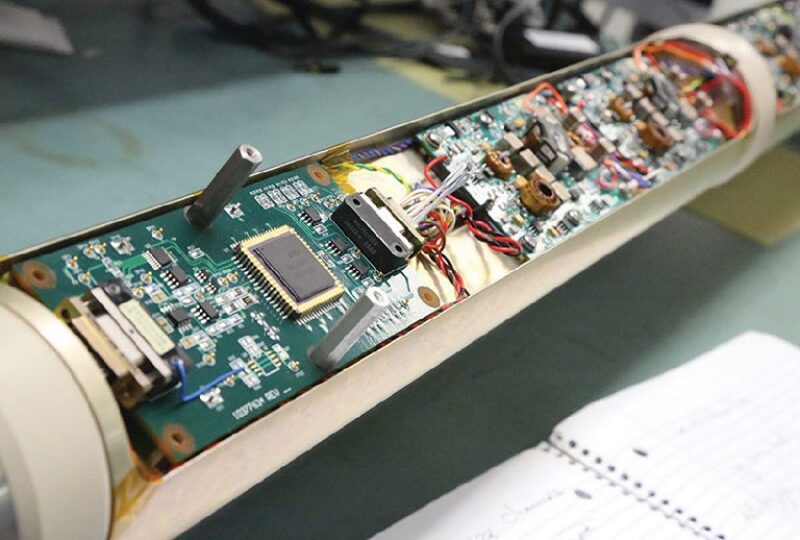
Reliability of electronic components in the hostile downhole drilling environment depends on myriad factors, such as how they are designed and manufactured, including the die-attach material and wire bonding; how they are populated on the board’s “real estate”; what type of solder is used; what type of material the tiny chip is housed in; and board material, thickness, and substrate, to mention just a few.
“It’s not easy to build high-temperature tools,” said Pedro Segura, mechanical engineering manager at Bench Tree, “and there are an excruciating amount of details that need to go right for them to work reliably.”
Hypothetically, Baker Hughes might want to build a circuit board with 100 components, Robert Estes theorized. Perhaps three of those components can be sourced from manufacturers such as Honeywell, Texas Instruments, or Cissoid that are known to work thousands of hours at 200ºC and above. “Let’s say our goal is to have that board operate at 175ºC,” proposed Estes. “So we’re very satisfied with these three components that are rated to 200ºC or higher.”
How are the other components sourced? “It could be that for 20 of them we could find a source of components rated to 175ºC. That was unthinkable 20 years ago—even 10,” said Estes. “But today, many suppliers will give us parts that will operate at 175ºC.”
According to Estes, “We have to tailor our design to use those components rather than a part that might be more efficient in doing the job, because we have to pick a part that will actually work. It’s a power drain, say, but it will work. Maybe it’s not as fast or the memory is not as dense.”
Furthermore, he explained, “Let’s say that takes care of 25% of the 100 parts. Now we have 75 other parts that we cannot get anybody to guarantee will even work at 175ºC. They may be a mix of 125ºC parts and 150ºC parts.”
What happens at this point in the board design process appears typical of all oilfield companies that build MWD/LWD tools. It is called component characterization. The information each company generates on each component it characterizes is considered its intellectual property and is therefore proprietary.
Identifying Components
In many instances, the industry is forced to use standard-temperature components well above their rated specification. In characterizing components, electrical engineers will find that some standard-temperature ICs will work at elevated temperatures. The process used to weed out those that will is tedious and time-consuming. Engineers must identify potential candidates, then test and characterize their performance over a long enough period of time to be certain of their functioning under the targeted downhole conditions.
“Electrical engineers read a lot about how an individual semiconductor is made,” said Paul Deere, president of Tolteq. “You can learn much more about what’s likely to be a good one to try.”
Deere mentioned some critical factors to consider when reading about semiconductor construction: “Long-term, you’re looking at the type of wire bonding that they’re using—they will all have a fire retardant in them. What types of fire retardants? Because those chemicals become caustic at temperature and then they start eating the chip or wire bonds away as well.”
Basically, he said, “when you run it at higher temperatures, the aging process accelerates.”
He cautions that you also have to look out for a phenomenon known as latching, whereby the effect of heat is so intense the semiconductor stops acting as it should and instead acts like a conductor. At that point, it would be rendered inoperable because it would not be able to perform the switching functions (i.e., conducting, then not conducting) it is designed for. “Sometimes it’ll burn up,” he said. “But sometimes if you cool it down, it’ll start acting like a semiconductor again.”
Matthew White said, “The challenge becomes trying to identify parts that were not originally designed, developed, and tested by the manufacturer to these temperatures, that actually are capable of operating to these temperatures. There are manufacturers out there that have really good manufacturing specifications and they use really high-quality materials and so we find that their parts—even some of the 85ºC heat-rated components—might operate at 150ºC and above.”
In general, what seems to fail in lower-rated parts is not the silicon chip itself, but the surrounding structures. “It’s the packaging for the IC,” explained White, “it’s the wire bonding between the IC and the legs of the IC. It’s the soldering between those legs and the printed circuit board. Sometimes it might be the glue that holds the silicon down in the packaging.”
White explained further that if the junction on an 85ºC rated part is good to 150ºC, this tells him that the silicon substrate is all right. The problem instead is with the material the chip is wrapped in. “So what can end up happening,” he said, “is sometimes you can purchase the silicon die directly, so it’s not glued down to the package, it doesn’t have all the wire bonding yet, it doesn’t have the package built around it.” That is a very expensive process, continued White, “so typically you’re not going to do that unless you’re really pushing the 175ºC envelope. That’s when you really can’t find the components that have the packaging that you need and you’ve got to do something else.”
Working Within Downhole Heat Constraints
With MWD/LWD tools, the electronics and the battery cannot get cooler than the ambient temperature in the downhole environment. In addition, the operation of the battery and the electronics generates heat. Heat generation inside the tool arises from resistors, which are dissipating heat, from the operation of semiconductor junctions—integrated circuits and transistors and different types of semiconductors that generate a small amount of heat whenever they function. This means that the temperature of the tool’s electronic components tends to be higher than the ambient temperature. The excess heat between the inside of the tool and the geothermal formation provides a little bit of a heat sinking effect.
Downhole heat management is a challenge. “It’s like trying to throw water outside a screen door on a submarine,” commented Don Lewis, materials manager of Koomey Controls Pressure Control Group at NOV. “One of the things you want to do to mitigate this effect is to operate on the lowest voltage and the lowest current you can.”
“You cut way back on how many processes you can execute downhole in the timeframe to conserve battery power and prevent heat dissipation,” said NOV’s Robert Warner. “We could do a lot more analysis or measurement types downhole, but due to the environment, we have to scale back.”
According to Matthew White, one of the areas designers look at is component packaging that has a good thermal coefficient of conduction “so you’re actually conducting heat away as best as possible. As well, how you lay out your printed circuit board will also help dissipate the heat away to the printed circuit board substrate.”
He added, “In some cases, you’ll do another layer of heat sinking where you’ll actually try and thermally connect the printed circuit board to your metallic chassis. All in an effort to pull that heat away from the IC itself and keep its differential between ambient and its temperature minimal.”
Designing Tools Using Multi-Chip Module (MCM) Electronic Components
Component Derating: Managing Electrical and Thermal Stress
Characterizing components involves a process known as derating. In Applied Reliability and Maintainability (R&M) Manual for Defence Systems, Part C—R&M Related Techniques, prepared for the UK Ministry of Defence and issued May 2012, derating is defined as “a policy of deliberately under-stressing components in order to provide increased reliability.”
Typically, the manual states, the components for which derating is applicable include transistors, resistors, transformers, integrated circuits, microelectronic devices, and other passive electronic devices with stress-dependent failure rates, such as capacitors and inductors.
The manual also states that the reason for derating is because of two types of stress that an electronic component is subject to: an electrical stress—with increasing tendency to break down due to voltage, current, or power—and a thermal stress due to its own power dissipation and, in part, to the total dissipation of neighboring components and/or the local environment. Reducing electrical stress will indirectly reduce thermal stress and lead to improved failure rates.
NOV Downhole electrical engineer Alamzeb Khan discusses a simple case with capacitors. “So you go with a very high capacitance that can withstand very high voltage. During operation, they’re not going to actually be giving that kind of voltage to the capacitor. It’s able to withstand way more than it’s actually given. The reason for that is that under high temperature/high stress, such components will degrade. … We’re using this capacitor, a pretty good part, in an environment that’s going to be way worse than what you started with. Sometimes the manufacturer says they can help you and other times they say they have no idea how it will work. So we have to do a lot of testing in house to determine what will happen.”
So a capacitor that is rated for 10 volts might be used only for 3 volts.
In another example, a digital signal processor (DSP) would be used at a much lower clock speed than its operating specifications, to ensure its reliability downhole and also to conserve battery power. “So we will run the DSP slow to keep power draw low as well as heat generation low,” explained Khan. Unlike a normal computer, there are no fans in the downhole computer to distribute the heat to ambient. “Actually the part is rated at 100 MHz or more and we’re going to run it at 16 MHz.”
“We have a limited amount of power due to battery life,” said Robert Warner. “You try to stretch as much out of the tool as you can to conserve power and heat so that you can get reliable and longer runs downhole. We have factors that other industries really don’t have to worry about.”
Further Design Issues
Because of space limitations, one does not get the benefit of isolating a lot of a board’s components from vibration and heat, said Warner. One reason is that you want to measure both vibration and temperature. Another reason involves awareness of board designs and layouts such that a component is kept in regions “that don’t cause degradation to it based on its mounting.”
Circuit cards are made of high-temperature materials like polyimide.
To keep the solder from melting and components from literally falling off circuit boards, high-temperature alloy solders are necessary. Because of the spreading adherence to lead-free regulations, called Restriction of the Use of Certain Hazardous Substances in Electrical and Electronic Equipment (known as RoHS), signed into law in the European Union on 21 July 2011 and which took effect 2 January 2013, several lead-free high-melting-point solders are widely available. Some examples of these include 96% tin/4% silver (Sn96Ag04) and Sn95Ag05, both of which have been used in downhole tools. Unfortunately, these may be less reliable at high temperature than lead-based solders.
Epoxies and other adhesives are used in staking components in place on the board. This gives it more strength because the leads (or legs) from the ICs could break or crack under the downhole environment. The aim is to try to relieve some of the mechanical stress points.
“An important aspect is strain relief on all wires,” said Aaron Schen. “There are no wires between boards or flying leads off boards. They always have some mechanical fixation to the edge of the board. Also, our boards all have very rigid mechanical frames that provide support.”
“There are more chances of failure in a longer board,” said Khan. This is due to additional flex seen during operation.
“You have to be very careful not to turn the board itself into a resonator,” explained Schen. “However, the biggest risk for vibration damage usually comes from heavier components. The physical law is force equals mass times acceleration. So for the same acceleration (g), the mass, as it goes up, the force goes up. Also, the heavier components create low-frequency resonances. The best analogy I can think of is a tuning fork. You don’t want a tuning fork downhole resonating at the same frequency as vibrations commonly encountered downhole.”
Finite element analysis modeling is then performed on the board. For resonance and vibration issues, said Schen, one would want to test at the board level.
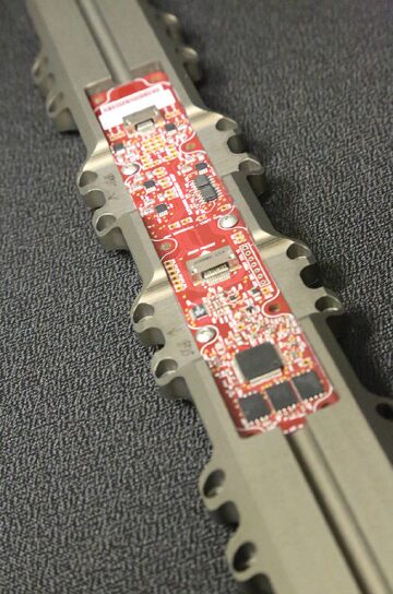
Circuit boards are far thicker than those used in consumer electronics. They typically have many layers containing circuit traces.
In addition, “Part of our design revolves around reducing the number of components,” said Khan, “because that reduces your failure points. So you try to accomplish as much as you can with the smallest number of parts on the board as possible. So another design challenge, apart from the trace fit and other issues, is to accomplish the most with the least.”
There are additional ways to mitigate shock and vibration. “You might have a flexible polyurethane bumper in the bottom of a tool so that when it takes a shock it has a gentle deceleration instead of a smack,” said Don Lewis. “You might suspend the sides of the board by some sort of elastomeric material like Viton and let the Viton take the shock and vibration a little.”
Downhole shock is unpredictable and severe. “When we talk about a drilling jar,” said Lewis, “we’re talking about a freight train collision.”
Testing Is Critical
Companies that manufacture MWD/LWD tools put a priority on ensuring system reliability before the tool goes commercial. Ryan’s Matthew White explains the process. “First you’ve got to do a lot of part selection where you’re making an educated guess that you think the part will work at temperature. If you select a part you’ve never worked with before, the first thing you do is build up a test circuit—something that will test the component’s basic functionality and how you’re going to use it in the fullblown system.
“You build the test circuit, bench test it, and verify that the circuit’s working properly. Then you put it in an oven and run it up to your desired ambient temperature and look and see how much temperature differential you’re getting and thereby determine its operating parameters. So it has to pass a basic functional test at temperature first. If it fails, you go back to the drawing board and pick another component. You do this over and over until you find the solution you seek.
“In some cases, you simply cannot find an off-the-shelf part—an integrated circuit—so now you have to start breaking it down and creating some of the IC’s internals on your own with discrete components. This means you’ll have more parts, which means you need more board space, which is certainly not desirable but in some cases it’s necessary because no other solution works.
“So let’s say you’ve identified a component that works at temperature in the oven—it survives. The next question is: How long do you think it will survive? So you leave it in the oven and run it for a period of time until you feel comfortable that it will last weeks, because an MWD tool’s going to tend to be downhole for 10 to 14 days straight in ambient.
“If that component survives that long-term heat test, the next question is: What happens if it was just that one component? So then you need to run 10. And you verify that even 10 were working correctly. Now you feel pretty confident that this part, at least from a temperature standpoint, will survive.
“Typically, by the time you do that, unless you have a really big part and you have some concerns about shock and vibration, you’ll go ahead and put it into your circuit, and design your entire circuit. Then you put it back in the oven as a system and you’ll verify that it’s working at temperature over a long duration.
“The next step, you’ll put it through highly accelerated life testing (known as HALT). Now you’ll not only run it at temperature, but you’ll thermally cycle it really quickly where you’re actually going to fatigue at a microscale all of the internal joints and connections and lower bonds on the printed circuit board and the glue and the entire chemistry of the system. You’re going to stress it the best you can.
“Then you’re going to apply vibration to see if anything will break. And you ramp that up over time until you see that it meets your specification. Finally you apply heat and vibration simultaneously to do your best to simulate what it might see downhole. Typically, when you do that, you will find something that failed at one of those test phases. You’ll go back and do some reengineering. You’ll understand what the problem was and correct it, whether that means a new component, a different printed circuit board layout, whether it was a wiring issue—whatever the issue. You solve that, come back and redo the test and you iterate that process until you feel that you’ve got something that’s reliable enough that you can put it in the downhole environment.”
Then the system is ready for field testing, because in-house environmental testing—however rigorous, sophisticated, and systematic—cannot fully mimic actual borehole drilling conditions.
Rick Campbell, sales manager at Bench Tree, adds, “As part of our testing team, we actually have an individual we hired as a third-party consultant. It’s his goal to break the board. Break everything we do. With that, that’s how we implement better procedures.”
“He’s the devil’s advocate,” said Aubrey Holt, president of Bench Tree. “We actually have the devil’s advocate’s teacher.”
Managing the Component Obsolescence Cycle
Electronic components typically have much shorter lifespans than the MWD/LWD tools in which they are used. A component’s market lifespan, from cradle to grave, could be as short as 2 years. Downhole tools might undergo 2 to 5 years of research and development, as well as in-house and field testing. Once commercial, a tool’s lifetime might be anywhere from 5 to even 15 years.
The process to find and characterize components that work reliably—in particular at temperatures of 150ºC and above—and that can endure the hostile drilling environment is arduous and painstaking. A company would prefer not to interfere with a recipe that is successful.
According to Todd Burke, senior executive at Smith & Associates, “You must have enough of those components on board to service the tool for the next 5 to 10 years.”
Smith’s role, like that of another company called Trendsetter Electronics, is to aid in managing the component obsolescence cycle for clients that include oil and gas MWD/LWD and wireline tool manufacturers and service companies as well as operators.
The company sources, documents (including reporting and traceability), tests, inventories, repackages (when necessary), and handles logistics of semiconductor and electronic components. It has 13 offices worldwide, with headquarters in Houston and logistics facilities in Hong Kong and Amsterdam. Smith works with approved vendors as an independent (as opposed to authorized or franchised) distributor. Its floors of traders gather global pricing and supply information as they locate hard-to-find parts and arrange to have them delivered quickly.
Obsolescence begins immediately after the original component manufacturer (OCM) issues information about discontinuance.
Obsolescence could mean any of a number of things: The OCM might issue a product discontinuance notice, end-of-life (EOL) or lifetime buy (known as an LTB) notification, or a product change notice. A component can be considered obsolete once it is no longer available from the OCM, even though parts are still in the supply chain.
Proactive obsolescence management occurs throughout the introduction, growth, maturity, saturation, and beginning decline phases of the component lifecycle. Reactive obsolescence management occurs from about halfway into the component’s decline phase, all the way through phase-out to actual obsolescence.
One must be very careful when making an open market buy, cautioned one oil and gas industry participant. “It is no underestimation to say that the open market can be very nasty,” he said. “There are all kinds of people who will say a component is legitimate when it is not.”
Combating a Major Threat to Reliability: Counterfeiting
The open electronics market is rife with some of the greatest enemies to component reliability: substandard, fraudulent, and counterfeit parts. This is the same electronics supply chain that brings the world its cell phones and tablets, workplace computers, crucial military equipment for intelligence-gathering or combat missions, and commercial aeronautics—now more electronic than hydraulic.
According to a blog written by Smith chief operating officer, Matt Hartzell, “Conservative reports identify well over 100 incidents of counterfeit components a month.”
One of the steps he identified to combat counterfeit parts was the National Defense Authorization Act (NDAA), passed by the US government in 2011. The NDAA requires defense contractors to tighten supply chain traceability and parts procurement to minimize counterfeit risk. At heart, the NDAA’s definitions of counterfeit components are geared to deter counterfeiting through tighter quality-measurement processes.
NDAA Section 2320 defines counterfeit as a “spurious designation” intended to deceive and infringe on US trademark law. Counterfeits are most basically defined as parts that are “marked” or “remarked” as something that they are not. NDAA Section 818 goes further and directs the US Department of Defense to establish a definition for counterfeit that must include parts previously used and then resold as new parts.
Hartzell writes, “This latter aspect of counterfeiting has become important because of the high number of obsolete or end-of-life parts needed to replace components in older systems, such as in aerospace, defense, oil and gas, and other industries with long-life machinery. EOL and obsolete components are prime targets for counterfeiters because of the high-value return from these high-mix, high-demand but low-volume parts.”
In an interview, Hartzell delineated how Smith & Associates notes initial indicators of possible counterfeiting. “In our experience,” he said, “initial questions about a product’s authenticity start with the product vendor.”
Smith’s first step is to evaluate and certify a vendor. This vendor screening considers factors such as location, reputation, facilities, and financial strength. Smith’s purchasing systems keep abreast of current pricing for each component. “Sharp deviations below those ranges are red flags,” said Hartzell.
The Future
According to Baker Hughes’ Robert Estes, “high temperatures in the oil field seem to go in jumps of 25ºC. And these jumps may take 10 years. This means it takes that long for sufficient component manufacturers to get that component available and for system integrators and service companies to actually build tools based on them and then to have a fleet that today is qualified to work at 150ºC, 175ºC. The goal now seems to be to work at 200ºC. And it’s very difficult.”
Estes cites the Arrhenius Equation, that says for every 10ºC increase in temperature, you double the failure rate in electronics. “At that rate,” he said, “it’s pretty easy to realize how you can make an electronic component that works reliably for years at room temperature. And then when you get as high as 200ºC, you have many, many doublings of failure rate due to temperature increases. So it’s not at all uncommon to find parts that will fail in 100 hours at 200ºC, whereas those parts at 150ºC are expected to last thousands of hours.”
Despite the challenge, however, there are many companies and individuals tackling the rigors of the demand. At the forefront of the worldwide push to develop electronic components in the 200ºC and higher range is the International Microelectronics Assembly and Packaging Society (IMAPS), which holds a high-temperature electronics international conference and exhibition annually, this year in Europe focusing on the High-Temperature Electronics Network (HiTEN). The HiTEN conference is held in alternating years with its North American counterpart, the International Conference on High-Temperature Electronics (HiTEC).
This year’s conference at Oxford in July brought together hundreds of researchers and practitioners in academia and industry from all over the world to present their findings on all styles of practical high-temperature electronics design and implementation, along with a variety of high-temperature application areas. Although the main semiconductor focus today of HiTEN is silicon and silicon on insulator, HiTEN also provides a conduit for the exchange and dissemination of information on all aspects of high-temperature electronics.
For Further Reading
SPE/IADC 163572—A New Measurement-While-Drilling System Designed Specifically for Drilling Unconventional Wells, by S.J. Krase, P.R. Harvey, M.W. White, and T.G. Earl, Navigate Energy Services, LLC (now Ryan Directional Services).
SPE 159737—Thermal Management of Electronics Used in Downhole Tools, by Sandeep Verma, SPE, and Quincy Elias, SPE, Schlumberger-Doll Research Center.
IADC/SPE 127413—MWD Failure Rates Due to Drilling Dynamics, by Hanno Reckmann, Baker Hughes; Pushkar Jogi, Baker Hughes; Franck Kpetehoto, Baker Hughes; Sridharan Chandrasekaran, TATA Consultancy Services; and John Macpherson, Baker Hughes.
SPE 56438—Reliable Electronics for High-Temperature Downhole Applications, by B.L. Gingerich, SPE, and P.G. Brusius, Honeywell Solid State Electronics Center, and I.M. Maclean, Expro North Sea Ltd.