The large number of floating production, storage, and offloading units (FPSOs) commissioned more than a decade ago now require offshore-asset-integrity management and maintenance. The FPSOs were originally designed for continuous service for periods up to 25 years. However, although designed to strict criteria, structural and hull-maintenance shortcomings have become apparent, prompting remedial actions or extensive offshore-maintenance campaigns. An offshore-dry-docking concept was developed to lift an FPSO out of the water without disconnecting it from its mooring system and leaving the flowlines connected. The stable working platform allows work access to the FPSO hull, appendages, and mooring system.
Introduction
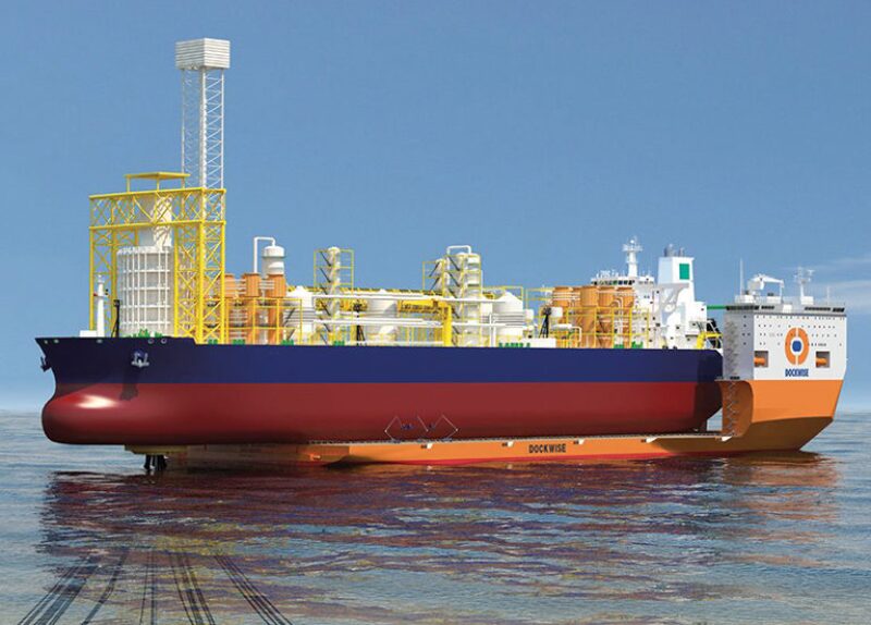
The proposed offshore dry-docking concept lifts the FPSO out of the water by submerging the floating dry-dock vessel and moving it underneath the FPSO offshore without disconnecting the FPSO from its mooring system or flowlines, as shown in Fig. 1 above. The bowless concept of the dry-dock vessel with a high load-carrying capacity enables dry transportation of more-traditional semisubmersibles and other floating production units and FPSOs. The proposed offshore dry dock investigated the use of dry-transportation technology for offshore dry-docking of complete floating production units.
Technical Specifications
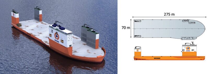
The largest heavy-transport vessel currently operating is designed to dry-transport offshore production facilities including ultraheavy semisubmersibles and FPSOs. In the past, an offshore unit would need to be wet towed from the fabricator to its production location. Scaling up the existing heavy-transport vessels was not sufficient because of the length of FPSOs, which can exceed 300 m. A bowless design is capable of transporting and offshore dry-docking FPSOs longer than 300 m, with the strength of the FPSO being the limiting factor. The design is shown in Fig. 2. With its bowless design, the total length of the Dockwise Vanguard (275 m) can be used. Its cruising speed of 12 knots is at least twice the speed of a wet tow. Floating cargoes with a maximum draft of 16 m can be loaded (not considering cribbing or grillage). The dry-dock vessel’s bowless design and the movable casings allow use of the vessel’s entire deck to transport units. Also, there are no vessel restrictions for overhang forward and aft. The bowless design is created by placing the crew’s accommodation on the extreme starboard side of the vessel together with the lifeboats.
Carrying Capacity. The capacity to dry-dock FPSOs is governed by the deadweight capacity of the vessel and the width and length of the FPSO. Deck-load requirements and stability are not considered critical in this case. The deadweight capacity of the Vanguard allows a payload of 117 000 t. Depending on the position of the center of gravity of the cargo, ballast water is required only for weight-offset compensation. With the FPSO overhanging the stern of the dry-dock vessel, it is expected that ballast water will need to be added to achieve zero trim.
The allowable width to accommodate an FPSO depends on the available width between the fixed accommodation block and the variable-position buoyancy casings. This width ranges from approximately 52 m to 65 m. The support length for supporting an FPSO is 275 m. Depending on the structural capacity of the FPSO hull girder, some overhang can be allowed, enabling the dry-dock vessel to accommodate FPSOs greater than 300 m in length.
Ballast System. The ballast system of the dry-dock vessel is a pump-based system selected for its potential to be adapted to ballast-water treatment. Such a system with sufficient capacity is not yet available. To achieve sufficient redundancy, the ballast system consists of a dual-ring line, serving all tanks, and dual pump rooms. The system is compliant with the latest regulations, including avoidance of crossflooding through vent lines in case of damage. All vent lines are routed to a safe zone, which will remain dry in case of damage, before venting in a central duct. To avoid pressures building up in tanks and the occurrence of water locks in the venting system, use has been made of drain tanks in the forward and aft ends of the vessel.
Compliance With Det Norske Veritas Heavy-Lift Notation. This dry-dock vessel is one of the first vessels to be built according to the Det Norske Veritas notation for semisubmersible heavy-lift vessels. The notation had a major influence on the design of the casings and the accommodation tower. The requirement to provide 4.5% of the submerged displacement as reserve capacity in submerged condition, and a minimum of 1.5% of the submerged displacement in each end of the vessel, resulted in additional freeboard.
FPSO Limitations. The deck capacity and carrying capacity of the dry-dock vessel will not limit offshore dry-docking of FPSOs. Two aspects that limit the concept are the dimensions and mooring system of the FPSO.
Dimensions. The dimensions of the deck are 275×70 m. The maximum width of the FPSO must be less than 65 m to install the safety and sea-fastening equipment. Clearance is required for maneuvering the FPSO between the casings of the dry-dock vessel and is necessary for repair work on the FPSO. A width of 60 m or less is preferred for loading, offloading, and performing repair work on the FPSO. The maximum length of an FPSO is limited by the strength of the overhang of the FPSO, the bending-moment capacity, and the static and dynamic loadings on the turret from moorings, risers, and flowlines. The largest FPSOs are 370 m long. These FPSOs will have an extensive overhang on both ends of the dry-dock vessel, potentially limiting access for inspection or repair work.
Mooring System. The offshore-dry-dock concept uses the mooring system of the FPSO to moor both ships. The most common mooring systems are internal-, external-, and spread-mooring systems. These systems are used by most of the current FPSOs. Both external and internal mooring systems are suitable for dry-docking. Spread-moored FPSOs have mooring lines in all directions, and some lines will need to be disconnected to avoid collision with the casings of the dry-dock vessel during loading and offloading operations. FPSOs with disconnectable turrets have not been assessed, and it is assumed that dry-docking onshore or near shore is more economical than an offshore operation.
Offshore-Dry-Docking Operation
The offshore-dry-dock operation can be divided into four steps. During all phases, the FPSO can stay on location and the turret system can stay intact. Scenarios considered for the feasibility assessment included the possibility for continued production and the configuration of moorings and the turret. Two scenarios were assessed.
- No production—all production systems and tanks emptied and gas free
- Limited production—direct offloading into shuttle tanker, with limited use of FPSO storage tanks
The following steps are for an FPSO with no production.
Prepare the FPSO. Preparation consists of emptying cargo tanks and freeing gas from them and depressurizing all processing plants onboard. An underwater inspection with a remotely operated vehicle is performed before dry-docking to determine the required work and to supply information necessary for loading the FPSO (e.g., protrusions). Cargo in the tanks will be offloaded to a shuttle tanker until no oil remains in the FPSO. After offloading is completed, all tanks must be cleaned and gas free. Risers must be depressurized and flushed.
Loading Operation. After both vessels have been prepared, the loading operation commences. This operation comprises approaching the FPSO, positioning the dry-dock vessel, and loading the FPSO. The loading operation is illustrated in Fig. 3.
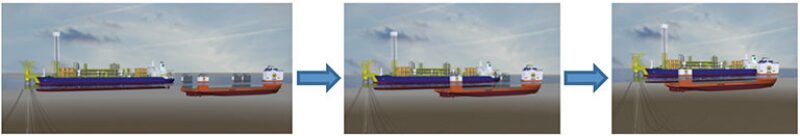
The FPSO remains on its position, and the dry-dock vessel is maneuvered by use of its thrusters and winches and by assisting tugs. After the initial load transfer is achieved and the floating assets are moving as an integrated body, initial utility and safety connections can be established. Once these connections have been established and confirmed to be in working order, the dry-dock vessel will deballast to dry-docking conditions.
Dry-Docking. The dry-dock-vessel/FPSO combination will be moored by the turret of the FPSO. The bow of the FPSO will overhang the stern of the dry-dock vessel, and the bow thrusters of the dry-dock vessel can assist in station keeping.
After positioning the cargo on deck, it will be sea fastened. Sea fastening keeps the cargo in position during the dry-docking stage. Permanent utility connections will be established to support the FPSO during the dry-docking period, including electrical power, water supply, waste and gray-water discharge, and cooling-water discharge. Lifesaving appliances and escape routing are installed to support both the contingent crew of the FPSO and the dry-docking labor during the dry-docking period. Logistics for the dry-docking work are put in place, including deck barges, accommodation barges, and standby safety vessels. Thereafter, the repair work can commence in favorable weather with modest movement of the dry-dock-vessel/FPSO combination. The scope of work during the dry-docking stage will include inspection, maintenance, and repairs.
Discharge. After completing the dry-docking work, the reverse of the loading operation can be initiated, implementing proper hold points to perform checks that would normally take place before leaving any dry dock.
Hydrodynamics of Offshore Loading and Discharge
Normal loading and discharge operations are performed in sheltered waters, resulting in limited environmental effects. Performing the same operation offshore leads to significantly higher loads and will affect workability. The main challenge during offshore loading and discharge is controlling the relative horizontal movements of the dry-dock vessel and the FPSO. Another specific hydrodynamic challenge during loading and discharge of an FPSO is to estimate the vertical movement when a very small gap exists between the FPSO and the dry-dock vessel.
Hazard-Identification Process and Safety Assessment
The hazard-identification study assessed the offshore dry-docking of an external-turret-moored FPSO as the base case considering no production from the FPSO and process equipment fully depressurized, but not necessarily gas free. The cargo tanks are gas free and made inert. General hot work is performed on the hull, but not the topside. Next, an internal-turret-moored FPSO was assessed, with the same considerations as the base case. The assessment of the spread-moored FPSO was not developed because the operating conditions were not fully defined.
A variation of the base case was assessed for external- and internal-turret-moored FPSOs to account for crude oil in the FPSO cargo tanks (no hot work, or hot work only in limited areas). No production would occur at the FPSO. Most tanks would not be gas free, and some tanks could contain cargo, although some operators may not permit dry-docking of a single-bottom FPSO with cargo onboard because of the potential of an oil spill if the bottom is damaged (e.g., by the cribbing).
Another case was assessed for reduced production to an attached shuttle tanker during dry-docking. Production might be shut down for a short period during the loading operation, but would be restarted directly from the production train to the shuttle-tanker export hose. The production rate would be significantly less than full production capacity. Cargo tanks would be emptied and made inert.
Conclusion
The main challenge during offshore-dry-dock loading and discharge is controlling the relative horizontal movements of the dry-dock vessel and the FPSO. The model test of a large semisubmersible showed positive results, providing confidence in the feasibility of the system. The mooring loads were within a realistic range for safe operation. Further model tests will be required to verify the relative movements during loading and discharge of an FPSO. The dry-dock vessel must be able to load and discharge the FPSO with a preferred significant wave height of at least 1.5 m to make it financially attractive in most cases. Areas with favorable wave characteristics would allow a maximum significant wave height of 1.0 m.
Use of a dry-dock vessel for offshore dry-docking can be of benefit when the FPSO is permanently moored by an internal or external turret and all lines have sufficient slack, repairs are related to the underwater portion of the FPSO and are accessible, significant advantages exist vs. executing an underwater repair, and no dry-dock repair yard is available within a relatively short distance.
This article, written by Dennis Denney, contains highlights of paper OTC 24330, “Offshore Dry-Docking of FPSOs: A Response to Industry Needs,” by T. Terpstra and E.A. Hellinga, Dockwise, prepared for the 2013 Offshore Technology Conference Brasil, Rio de Janeiro, 29–31 October. The paper has not been peer reviewed. Copyright 2013 Offshore Technology Conference. Reproduced by permission.