The Greater Burgan field began producing in 1946. It remains under primary depletion with natural waterdrive. Subsurface modeling is an integral part of reservoir management. In 2001, the first comprehensive full-field geological model was built with 65 million cells, encompassing all of the major reservoirs. A reservoir-simulation study (1.6-million-cell dynamic model) was conducted in 2003 by use of parallel-simulation technology. During the last decade, active field-development plans have resulted in major surface-facility upgrades and the drilling of +more than 300 new wells. This paper discusses scaling up the high-resolution geological model and specific problems encountered by the study team.
Introduction
The Greater Burgan field is in southeastern Kuwait, with an area of 320 sq miles. Fig. 1 shows the five main reservoir units of the Greater Burgan field complex: the Wara sand, Mauddud, Burgan Upper sand, Burgan Middle sand, and the Burgan Lower sand. Areally, the field is separated into three producing areas, Burgan, Magwa, and Ahmadi. Mauddud, the only carbonate reservoir in the sequence, is relatively tight and, together with the extensive Wara shale, acts as a barrier separating the Wara sand from the massive sands of the underlying Burgan formation. However, extensive faulting prevents communication between the Wara and Burgan sands.
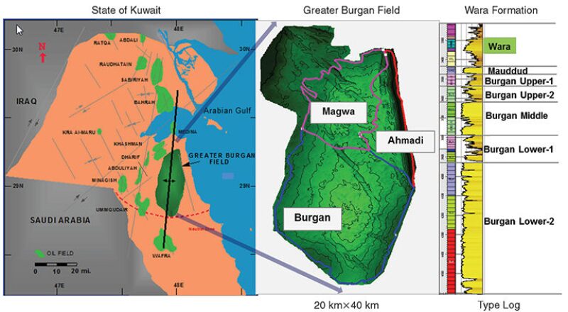
The Burgan oil field was discovered in 1938, with first oil production in 1946. Burgan has good energy support from strong natural aquifers, and after 66 years of production, most of the field is still under primary depletion. More than 1,200 wells have been drilled across the field. While drilling spacing is dense in the crestal area, well control in the flanks is relatively weak, giving rise to more geostatistical uncertainty. As the field has matured, the reservoir pressure has declined, reducing productivity.
Scaling-Up Approach
Because the field comprises significantly different reservoir units, a detailed geological description is required. A very-fine-scale geological model with 900 million cells was required. This geological model was constructed as a master model integrating all types of data available, and will be maintained and updated over time with new data from drilling, production, and other activities. For dynamic modeling, the very-fine-scale geological model is too big and must be scaled up.
A multiscale approach is needed for the Greater Burgan field. Several studies, including reservoir management and optimization, facilities design and planning, recovery optimization, and enhanced oil recovery, are envisaged for the field. These studies are expected to require different resolutions and different levels of reservoir-description detail. Use of a single model with the highest possible resolution for all of the studies is impractical for a field this size. Thus, each study had to formulate model-resolution requirements in accordance with the phenomena to be studied, which resulted in different scaling of the models.
Of these models, one is the master model and is used for the flow simulation. Choice of model size in this case was dictated by reasonable turnaround time, which in turn warranted that model history matching could be completed on schedule. However, certain aspects of field redevelopment could require a finer-resolution model, here called the Finer model, and should benefit from the groundwork of the Coarse master model.
The Coarse master model is used for full-field history matching and is expected to capture the general energy balance and the water-front movement. It can be used to generate reliable production forecasts for certain redevelopment scenarios such as infill drilling and waterflood. However, the reliability of the forecast profiles is expected to be limited to the regional level. Resolution of the Finer model would enable accuracy beyond the regional level (i.e., the Finer model is expected to produce the cube of remaining-oil saturation that can be used for actual well planning and water-injection design). In addition to the Coarse and Finer models, the team also proposed the use of an even coarser model with resolution just high enough to capture the major geological features of the Greater Burgan field. This Very Coarse model can be used for fast-track screening and sensitivity analysis, as well as for computer-aided history-matching exercises.
Areal scaleup, or upgridding, is needed for the model. In most reservoir-simulation studies, scaling up is performed only in the vertical direction because areal grid size of the geological model is already suitable for simulation. However, the immense size of the field, the depositional-environment variation within each stratigraphic unit, and the major differences in the degree of heterogeneity between different reservoir zones require the geological model to retain geological features at the highest possible level of detail, which results in small grid-cell sizes of 50×50 m.
Special attention must be given to reservoir connectivity. The degree of heterogeneity differs significantly from one stratigraphic unit to another, particularly when comparing the two main reservoir units: Wara sand and Burgan Third Middle sand. Burgan Third Middle sand is associated with a channel belt and is a clean massive sand, well-connected both laterally and vertically. The Wara sand has features of depositional environments from distributary channels to the tidal shallow marine with individual sand bodies with less width and often separated from their neighbors by tidal flats and shales. However, in a structured grid, the same areal dimensions must be used for the entire productive interval, which links the choice of the areal grid-cell size with the possible effect it may have on reservoir connectivity of heterogeneous reservoirs in a scaled-up model.
Model-Size Determination
The size of the master (Coarse) model was linked directly to the simulation model run on the operator’s hardware. Requirements for the model run time were formulated upfront. To meet the deadline, it was agreed that turnaround time of a history-match simulation run should be within 1 day. This requirement translates to a run time between 15 and 20 hours, with additional time for post-processing and analyses.
It is worth mentioning that the start of model scaling up coincided with the deployment of the operator’s new PC cluster. To estimate the optimal size of the Coarse dynamic model, a series of benchmarking runs was performed with different numbers of CPUs on the new cluster using the 2009 Greater Burgan parallel model (1.6 million cells). The resulting run time was used to estimate the run time required for the Coarse model, assuming scalability of run time with model size and CPU use. Benchmarking indicated that the optimal choice was 32 CPUs, which corresponds to a model size of 2–3 million cells.
The sizes of the Finer and Very Coarse models were derived from the numbers accepted for the Coarse model. Thus, the Finer grid had approximately 30 million cells, while the size of the Very Coarse grid does not exceed 0.2 million cells.
Upgridding
Although three grids of different resolutions (Coarse, Finer, and Very Coarse) were generated, the focus here is on the Coarse model because it was chosen as the master model for the study.
Areal cell size of the dynamic grid was selected on the basis of simple practical considerations. Ideally, while coarsening the grid, one should fit as many grid cells as possible between two neighboring wells. However, there will always be a compromise between lateral and vertical resolution of the grid. Areal grid-cell size of the geological model is 50×50 m. Therefore, the choice of areal grid-cell size for the Coarse dynamic model was restricted to between 100×100 m and 300×300 m. The average distance between wells in the field is approximately 500 m; thus, use of 300×300-m grid cells was not recommended because it leaves a maximum of one cell between two wells.
A 100×100-m grid resulted in at least four cells between two neighboring wells. However, to comply with a model size of 3 million cells, the 100×100‑m grid would require sacrificing vertical resolution. In the process of upgridding, every 15 geological-model layers had to be merged into a single layer of the Coarse grid. The vertical resolution of such a grid was deemed unacceptable for adequate representation of field geology, especially in the more-heterogeneous reservoirs such as the Wara.
Therefore, use of the 200×200-m grid appeared to be a reasonable compromise. It allowed at least two cells between most of the neighboring wells, but did not require significant coarsening of the grid in the vertical direction. On average, areal grid-cell dimensions of the Coarse grid would be 200×200 m, with a cell thickness of approximately 12 ft. Lateral coarsening of the grid was performed by rerunning the pillar-gridding process with the areal size set to 200 m.
For vertical coarsening, a variability-based approach was used (i.e., layers were merged together on the basis of the similarity of property distribution within the layer). A reservoir-quality index (RQI) was used for variability analysis. The RQI distribution within each fine-grid layer was presented as a proportion to the grid cells falling inside predefined bins of RQI and was visualized in the form of vertical-proportion curves for each zone of the model grid.
Layers that demonstrate similar distribution of RQI then were selected for merging. Technically, remapping was required for zones in the Coarse grid such that each of the new zones contained only layers intended for merging. In an attempt to preserve the conceptual depositional framework reflected in the geological-model layering, layer lumping was performed that used exactly the same layering scheme (i.e., proportional, follow top, or follow base) as was used originally for this zone in the geological model. Grid coarsening thereby preserved pinchouts and dipping angles defined by geological modelers in each of the particular stratigraphic units of the model.
Scaling Up Model Properties
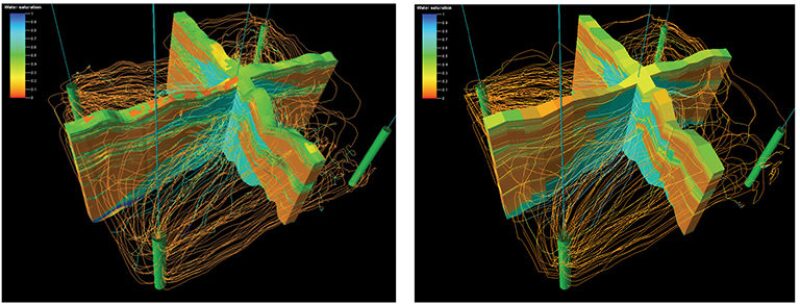
Before scaling up, the team conditioned the geological-model properties. First, two cutoffs were introduced to differentiate between reservoir and nonreservoir cells in the geological model. Any cell with porosity less than 2 porosity units or permeability less than 0.1 md was considered nonreservoir. Then, a binary-distributed (0 or 1) net-to-gross (NTG) property was created: All nonreservoir cells were assigned a zero NTG, while the rest of model cells had a unit NTG. Subsequently, NTG was used as a weighting factor for scaling up porosity, permeability, and saturation. Permeability and saturation-computation properties were given special attention in the property scaling-up process. Different algorithms were examined, and choice of the most-suitable algorithm was made subject to validation by streamline simulation on a sector model, as shown in Fig. 2.
Regarding water saturation, the team considered several ways of transferring saturation values from the geological model to the simulation model. In the geological model, water saturation was populated by use of three relationships derived from core-analysis data:
- Irreducible-water saturation as a function of RQI
- Maximum capillary pressure as a function of RQI
- An equation that links water saturation with normalized capillary pressure and with RQI
Multiple possibilities were available for repopulating water saturation in the scaled-up model, from direct scaling up of geological-model water saturation to calculating water saturation from the scaled-up rock properties. The complete paper details the permeability and water-saturation scaling-up process.
Quality Check
Quality checks were performed at each step of the scaling-up process. First, grid-cell geometry needed to be checked during the upgridding, This was necessary because areal upgridding requires reperforming the pillar-gridding step, which may result in irregular cell geometries. The inside-out check resulted in negative volumes and unfavorable cell angles, leading to highly twisted and distorted cells. Cells with irregular geometry needed to be identified and fixed, or flagged to be deactivated during simulation, to prevent potential problems.
Second, areal scaling up coarsens the grid and, consequently, reduces the resolution of the zigzagged faults. Part of the fault plane could be shifted slightly. If a well penetrated the fault plane or was in the vicinity of a fault, the well could appear on the incorrect side of the fault because of the fault shifting. The result would be incorrect formation markers or perforated intervals. This problem had to be fixed during scaleup. To fix the problem, wells were shifted slightly to the correct location relative to the fault.
Third, validation of the volumetric and flow-property conservation was needed. Of the multiple approaches to determine water saturation, the best approach was selected on the basis of volumetric validation. Flow-property conservation was validated by running streamline simulations on both fine and upscaled sector models to check whether reservoir connectivity was preserved. Because of the substantial heterogeneity in the Wara formation and significant scaling up, this check became very important.
Conclusions
To succeed, the scaling-up process required the use of an elaborate approach for grid coarsening and scaleup/transfer of the properties from the fine-scale static model to the coarse simulation grid. The following solutions were used:
- Multiscale approach (i.e., scaling up to dynamic models of different size).
- Upgridding that combined both areal and vertical (variability-based) coarsening. Use of the original (geological-model) layering scheme that allowed preserving geological input into the gridding process.
- Translating fine-scale water-saturation values to the coarse model, ensuring necessary preservation of model volumetrics.
- Use of mechanistic modeling at different stages of the scaling-up process.
The Burgan geological model was scaled up successfully to a dynamic model at three different scales. The approach chosen for the scaling-up procedure proved its value by demonstrating small-to-negligible discrepancy in volumetric comparisons between the fine and coarse models. This holds true for the results of the permeability validation that used streamline simulations on sector models.
This article, written by Senior Technology Editor Dennis Denney, contains highlights of paper SPE 164187, “Answering the Challenge of Scaling Up a 900-Million-Cell Static Model to a Dynamic Model—Greater Burgan Field, Kuwait,” by Eddie Ma, SPE, Kuwait Oil Company; Sergey Ryzhov, SPE, Schlumberger; Yuandong Wang, SPE, Petrobras; Reham Al-Houti, SPE, Laila Dashti, SPE, and Farida Ali, Kuwait Oil Company; and Muhammad Ibrahim, SPE, Schlumberger, prepared for the 2013 SPE Middle East Oil and Gas Show and Exhibition, Manama, Bahrain, 10–13 March. The paper has not been peer reviewed.