
The M4-field reservoir is approximately 2000 m below sea level in a water depth of approximately 120 m. A carbon dioxide (CO2) geological-storage study was carried out to determine the feasibility of injecting and storing CO2 in the depleted M4 carbonate gas reservoir. The study used 3D coupled-geomechanical modeling. The water level in the reservoir has risen close to the caprock, which implies a strong aquifer. Laboratory tests were carried out on core samples before and after injecting CO2-saturated brine solution, and the results were used to determine material-strength and elastic-property degradation caused by acid/carbonate interaction.
Introduction
Controlling the trapping of CO2 in the subsurface is fundamental for safe geological storage of CO2. Rock formations can be impervious enough to act as flow barriers to CO2 over geological periods of time. Delineating such a seal, safeguarding its integrity under operational conditions, and verifying its isolation effectiveness are key objectives in achieving a successful CO2-storage project.
During CO2 injection, the increasing fluid pressure, temperature variation, and chemical reactions between the gas and rock will inherently affect the stress state of the reservoir and its surroundings. Also, the rock mechanical properties may be altered by exposure to CO2 or by pressure and stress changes. Further, rock mechanical properties, pore pressure, in-situ stresses, and the stress evolution under injection conditions control reactivation of a fault and, therefore, risk of fault-seal breach. The effect of the resulting stress and pressure change, the associated caprock deformation, and the fault-seal integrity must be assessed to manage containment performance and leakage-related risks properly.
To address these issues, a good understanding of the flow dynamics, in-situ stresses, pore pressure, and rock mechanical properties in the field is necessary. The fracture initiation, propagation, and containment in the injection zones, and caprock and fault-seal integrity, are related to the in-situ stresses and the coupled pressure/thermal behavior while injecting.
Rock-Property Tests
A comprehensive program of mechanical- and petrophysical-property tests was conducted on selected overburden-shale and reservoir-limestone cores from Well A-2. The tests evaluated potential interaction between injected CO2 and the reservoir rock and caprock that could result in a change in mechanical properties of the rock materials and affect CO2 storage and containment.
Shale samples from two core depths and limestone samples from three core depths were tested. The study consisted of comprehensive evaluation of near-identical sets of samples from each core depth. One set of samples was tested without being treated with CO2, while the other set of samples was tested after CO2 injection to simulate reservoir-injection conditions. A standardized CO2-injection procedure was used in an effort to quantify the potential effect that CO2 injection has on shale and limestone properties under controlled test conditions.
Petrophysical Properties
Pre-CO2-injection porosity was determined for correlation purposes in conjunction with the pre-CO2 pore-volume-compressibility tests for the limestone samples. Identical samples were used to determine porosity and permeability following treatment with CO2-saturated brine for preinjection-treatment comparison and for correlation purposes with the post-CO2-treated pore-volume-compressibility tests.
Porosity of the limestone samples was determined, following cleaning, by measuring the pore volume at a nominal stress and at effective mean in-situ stress conditions. Then, permeability to gas was measured at the same stress conditions. Uncleaned samples were used for the pore-volume-compressibility tests conducted under uniaxial-strain conditions. For each test, porosity was corrected for the volumetric deformation that occurred during reapplication of the net effective mean in-situ stress.
Pulse-decay permeability tests were carried out on two samples from each shale-core depth. One sample from each depth was subjected to CO2-injection treatment, followed by a pulse-decay permeability test for comparison with the untreated sample. High-pressure mercury-injection porosimetry tests were performed on two samples from each shale-core depth. One test was carried out on an untreated sample, and the same test was repeated on an adjacent sample following CO2-injection treatment.
Coupled Modeling
After the initial stress state had been established in the 3D geomechanical model, analysis was continued with the evolution of pore-pressure changes caused by production and CO2 injection. Several stress steps were selected during the schedule at which the pore pressures calculated by the reservoir simulator were passed to the stress simulator and equilibrium was re-established. In addition to the calculation of stress at each step, volumetric strains were calculated and related to a change of porosity. These porosity changes led to modifying the permeability in accordance with pore-volume-compressibility tests carried out on three samples in the laboratory. The laboratory tests were carried out in compression only; however, because the reservoir was likely to expand during CO2 injection, the exponential curve was extended to include tensile volumetric strains.
Increases in permeability resulting from the effects of acid/carbonate interactions were accounted for on the basis of the results of pre-CO2-treated and post-CO2-treated samples. Permeabilities were enhanced by 30% of their initial values, scaled to the increase in CO2 saturation predicted by the reservoir simulator.
To account for the effects on the elastic and strength parameters of acid/carbonate interactions resulting from the injection of CO2, the material properties were continually updated as the coupled analysis proceeded. The mechanical material parameters were updated in accordance with the results of laboratory tests on specimens saturated with a brine/CO2 solution. Brine/CO2 flooding of the samples was considered to have produced 95% CO2 saturation. The magnitude of material-parameter degradation was scaled to that determined from laboratory tests on the basis of the CO2 saturation predicted by the reservoir simulator.
After a material’s elastic and strength properties were deemed to have degraded, the change was considered permanent. There was no subsequent increase in elastic/strength properties should the CO2 saturation be reduced during the schedule.
The initial average reservoir pressure was 3,850 psi in May 1992, which declined to 2,890 psi in 2015 with production, in accordance with the reservoir-simulation schedule. Two CO2-injection scenarios were considered. Scenario 1 included four injection wells, each injecting at a rate of 50 MMscf/D to 2028 whereby the reservoir pressure was brought back to the initial, preproduction condition. Scenario 2 considered two injection wells, each injecting at 100 MMscf/D continuously to 2065.
The variation in predicted gas saturation for Scenario 1 was used to control the degradation of material properties for an upper reservoir layer. CO2 injection was initiated in 2018, and the saturation increased to a maximum value in 2028 and then declined during the monitoring period.
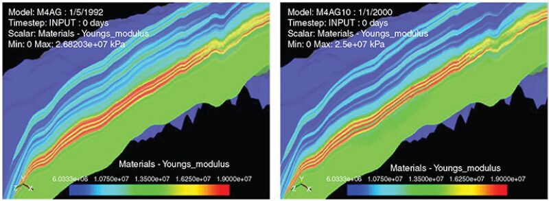
The resulting variation in derived CO2 saturation reduced the elastic and strength properties. The reduction in Young’s modulus between 2017 (end of production stage) and 2028 (peak injection) for Scenario 1 on a section through the reservoir is shown in Fig. 1. Further degradation of material parameters was calculated during Scenario 2 in which the injection rate and injected CO2 volume was considerably higher.
A major objective of the study was to determine whether caprock integrity would be breached during CO2 injection. An examination was made of the increased shear stresses within the caprock during the injection period. Large increases in shear stress could cause material failure in the form of shear bands or fracturing. This failure must be avoided to prevent injected CO2 being vented to the atmosphere. Fig. 2 shows the increased shear stress within the caprock caused by injection.
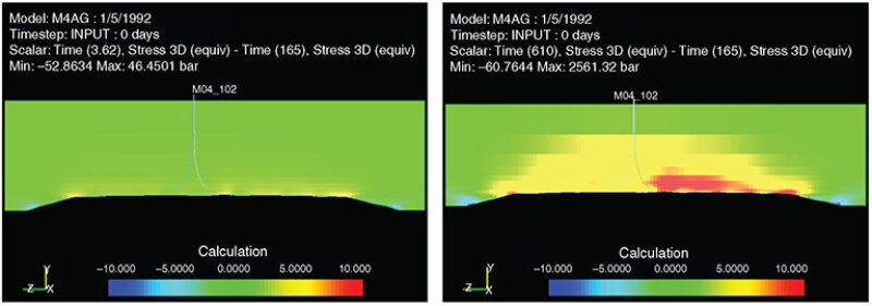
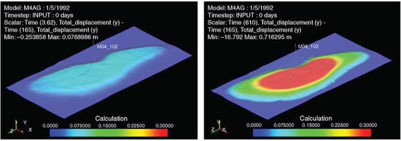
Shear-stress changes in the caprock generally were not significant, although they were considerably larger for Scenario 2 because of an isotropic change in effective stress caused by injection. Shear-stress magnitudes for both scenarios were not large enough to overcome the shear or tensile strengths of the overburden formations. Corresponding vertical displacements at the top of the reservoir are shown in Fig. 3.
Changes in stress caused by both production and injection within the reservoir for Scenario 1 were small enough that the Mohr-Coulomb failure criterion was not reached at any point, indicating that the injection pressures could be withstood. However, the large injection pressures in Scenario 2 produced shear and tensile failure within the reservoir. Fig. 4 above shows the development of large plastic shear strains of more than 3% in the vicinity of the injecting wells in 2055. Plasticity occurred over almost the entire width of the reservoir, indicating a complete breakdown of the intact rock for this volume of injected CO2.
Conclusions
On the basis of the rock mechanical- and petrophysical-properties test program, it was observed that there is a reduction in Young’s modulus, unconfined compressive strength, angle of internal friction, and tensile strength, while there is an increase in Poisson’s ratio and permeability for the post-CO2-treated test samples.
This article, written by Senior Technology Editor Dennis Denney, contains highlights of paper IPTC 16703, “Simulation of the Chemical Interaction of Injected CO2 and Carbonic Acid Based on Laboratory Tests in 3D Coupled-Geomechanical Modeling,” by Rahim Masoudi, SPE, and Mohd Azran Abd Jalil, Petronas; Chee Phuat Tan, SPE, David Press, SPE, John Keller, and Leo Anis, SPE, Schlumberger; and Nasir Darman and Mohamad Othman, SPE, Petronas, prepared for the 2013 International Petroleum Technology Conference, Beijing, 26–28 March. The paper has not been peer reviewed. Copyright 2013 International Petroleum Technology Conference. Reproduced by permission.