Throughout my nearly 40-year career in the oil and gas industry, I have followed the evolution of produced water treatment. In trying to keep pace with the changing industry, my recollection of the past grows dim, but the perspectives gained over time have provided me with a clearer look into the future. Over a 60-year course, produced water treatment technologies have progressed from primitive to the most sophisticated methods of separation.
In an industry founded on opportunity, the early goal of oil and water separation was to provide the most pure oil in the sales line with less consideration to clean water for discharge. Fortunately, the offshore industry in its infancy (1950s) was able to prevent the environmental scars found in industries in which improper waste disposal was a common practice. This was due, in part, to the self-policing practiced by major oil and gas companies.
There were few regulatory restrictions in the 1940s and 1950s. Although efforts were made at that time to improve the handling of produced water and produced sand, there remained a stigma regarding the way these materials were disposed of, with the methods being primitive and generally ineffective. Because of a lack of attention to water phase treatment, little effort was given to improving gravity separation. Therefore, the separated materials were disposed of improperly.
The first regulations applicable to the discharge of oily water were instituted in the 1960s. Operators had to ensure a “no slick/no sheen” discharge. Compliance to the regulations was self-imposed and self-monitored via visual inspection.
Large tanks were used as the first attempt at gravity separation, but were inefficient and required much space. It was an acceptable method of monitoring the discharge of water and sand and it generally worked as long as the operator was able to provide sufficient retention time for the separation to occur. The technique somewhat cleaned the water phase, which would then be discharged to the ocean, with the oil and gas undergoing further processing.
As the industry matured, oil production increased, as did the produced water and sand. Installation of an adequate number of retention tanks to handle the increased production became difficult in the limited space available on offshore platforms. Instead, retention times for separation were decreased, resulting in increased levels of ppm at discharge.
Although it took time for the industry to embrace improved methods, technology took strides toward improvements in the late 1960s.
Plates Improve Gravity Separation
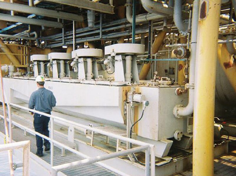
A Dutch company, Pielkenrood, was one of the first to provide tilted plates to improve standard gravity separation. At the same time, Shell developed a similar device, called the corrugated plate interceptor (CPI). An example is shown in Fig. 1. It used closely spaced plates along with a corrugated geometry to shorten the distance of rise of a separated and free oil droplet, improving the efficiency of the gravity separation process. Placing the plates at ¾-in. spacing on a 45° angle offered the best way to improve separation without premature plugging from solids.
Companies such as Engineering Specialties and Monarch embraced the technology and designed containment for the “plate pack,” which separated solids and oil into compartments in the vessel. The designs offered enhanced separation capability while decreasing the overall footprint of the equipment.
More improvements followed, one of which was the SP Pack. Developed by Ken Arnold, the unit coalesced oil droplets for further improvement to the separation process.
Continued and increased oil production brought increased water and solids production as the fields aged and became the next driving force for enhanced performance.
Introduction of Induced Gas Flotation
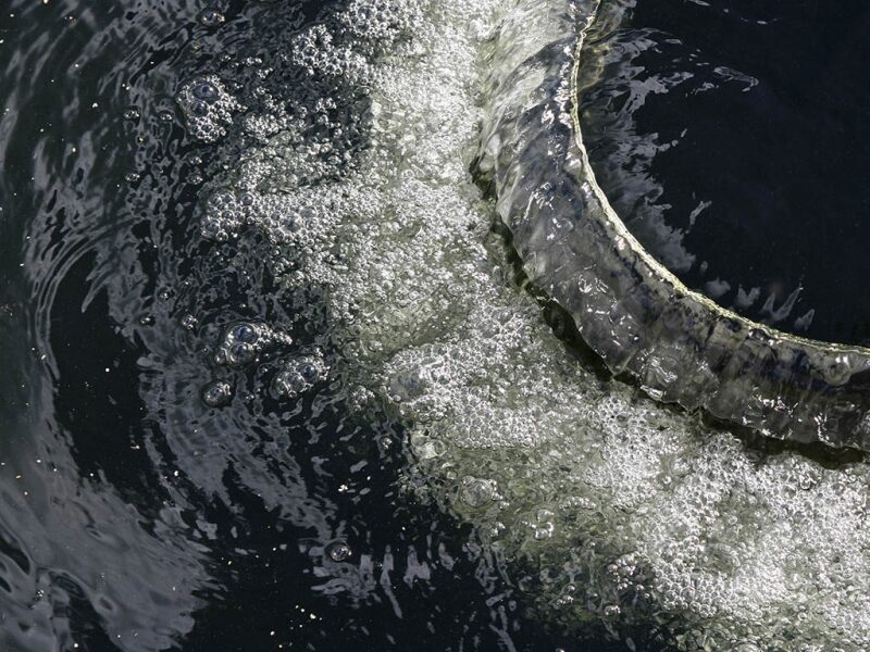
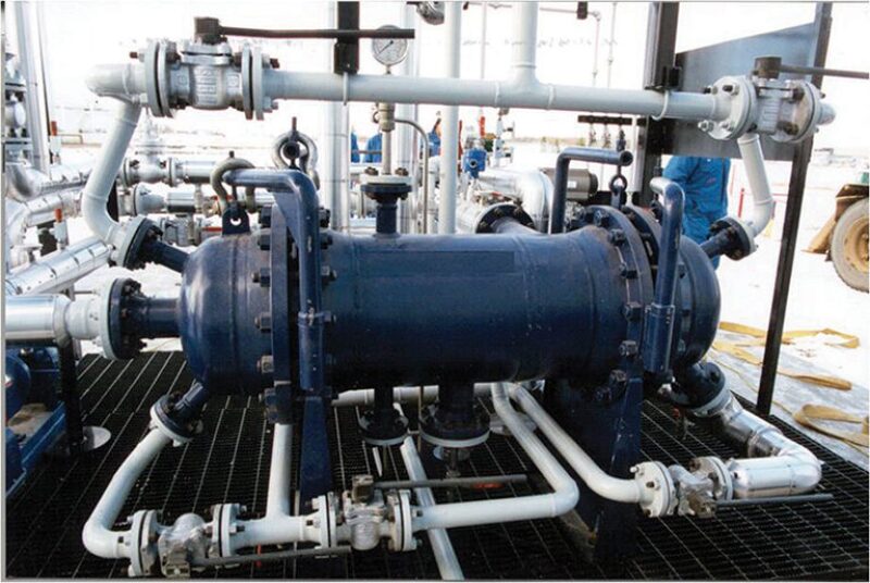
A secondary separation step was developed by National Tank. Installed as a retrofit, a bolted tank was used as the first induced gas flotation unit (IGF). An example of an IGF is shown in Fig. 2.
Gas bubbles were introduced into the stored water to attach to oil droplets and accelerate the rise of the droplets to a collection surface. Unfortunately, because of the inability to generate small gas bubbles and the vertical design of the tank, separation of oil from the water was inefficient.
I saw this first attempt at using IGF in the early 1970s on an offshore platform while working for Shell. I returned to the same platform several years later and found the same tank turned into a tool storage room.
After the first trial period for IGF in the early 1970s, operators continued to seek separation methods with improved efficiency.
Monosep, a small company owned by Al George of Lafayette, Louisiana, worked on a single cell flotation method to help improve separation before disposal. The unit had a novel horseshoe design incorporating a single eductor and a recirculation pump. Later, the company made additional improvements by enlarging the vessel and including multiple cells for stage separation. The design became the forerunner for the hydraulic-style flotation cell.
During this same period, Western Equipment Manufacturing (WEMCO), a firm founded in the mining industry, was creating a process called mechanical flotation for the removal of fine solids particles for clarification of mining wastewater and the collection and recovery of valuable minerals such as gold and silver.
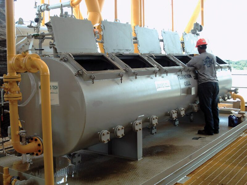
According to anecdotal history, a Shell engineer on assignment in western United States saw the WEMCO equipment in operation and surmised that it could be applied to oil/water separation (Fig. 3). This mechanical method offered a powerful method of lifting the solids particles to a collection surface before removing them from the wash water process for reclamation, thus creating a benchmark for produced water processing.
Two IGF methods, similar in principle but different in design, were in use: the mechanical IGF and the hydraulic IGF. The efficiency of the hydraulic design closely followed that of the mechanical design, but has gradually improved over the past 30 years.
Outside of the first Monosep multicell IGF, WEMCO also created a hydraulic nozzle air design. It was essentially the same machine as the mechanical WEMCO without the mechanical agitation. Both companies used a recirculation pump to recirculate the cleanest water to the eductor system to create the bubbles. Both units had four cells, 5 minutes of retention time, similar box geometry, and mechanical paddles to remove the collected oil froth.
In the late 1970s, Dresser Di‑Chem introduced a version of the hydraulic IGF, called Tridair, which had a smaller footprint and improved recycle design. With an under and over baffle design, the Tridair was readily accepted as an improved water processing method. From the time of its introduction to 1982 when Dresser Di-Chem sold Tridair to Engineering Specialties, there were more than 300 units operating in the Gulf of Mexico and around the world.
Up until then, each company and product stood alone and on its own merit. It was understood that each offshore process might require its own solution and therefore, at that time, there was no linkage of the CPI and IGF.
Discharge Limits Drive Water Treatment Technologies
Engineering Specialties was one of the first companies to recognize that a water treating process was likely to become necessary to meet the rigors of the new federal regulations on the horizon. As the industry learned more about processing the overboard fluids, it was finally understood that no one piece of equipment was the answer to the problem. It was determined that a combination of equipment in series may be required to meet the tougher regulations.
The Minerals Management Services (MMS), a bureau of the US Department of the Interior, was charged with regulating discharges from offshore platforms. The bureau set a fixed discharge number of 72 ppm of oil and grease in water. It was a significant step to further improve discharge requirements for federal and state waters in the US and worldwide. The new target put operators on notice that a subjective approach to monitoring discharge was no longer acceptable. By instituting a quantifiable limit that was to be reviewed monthly by MMS, operators were expected to be vigilant about compliance. In actual practice, however, MMS and the operators did not routinely police for compliance. In spite of the fact, the industry was moving in the right direction.
As technology improved, MMS took notice of the improvement and lowered the discharge limit from the 72 ppm and 48 ppm in the 1980s to today’s limit of less than 29 ppm. Because of more stringent regulations, operators were forced to find an overall solution to water discharge problems.
In the mid-1980s, Uncas Favret and I, employed at Engineering Specialties, determined that a combination of technologies would be more effective than standalone equipment in water processing. The company applied and received a patent to use CPI in conjunction with an IGF as a method to process and remove oil from water to meet the federal regulation of less than 29 ppm. It worked.
Kerr-McGee provided Engineering Specialties with the first opportunity to test and evaluate this theory in the Gulf of Mexico Breton Sound area. The CPI plate separator and the Tridair IGF combination became the benchmark for process water treatment. Additionally, the company’s Sumperator/Skim Pile product served as a final disposal for not only deck drains, but also the treated produced water from the process system.
PaceSetter and WEMCO also provided combined CPI and IGF methods, and U.S. Filter purchased Lancy Separators to attempt to develop a similar treatment scheme. An enhancement to the CPI/IGF concept was the addition of filtration downstream of the IGF for tertiary treatment when reinjection came into vogue.
There is a thought process that the conventional technology of the 1970s has made full circle by taking us back today to the same principles for separation. Fortunately, there have been improvements, making the products more efficient and easy to use.
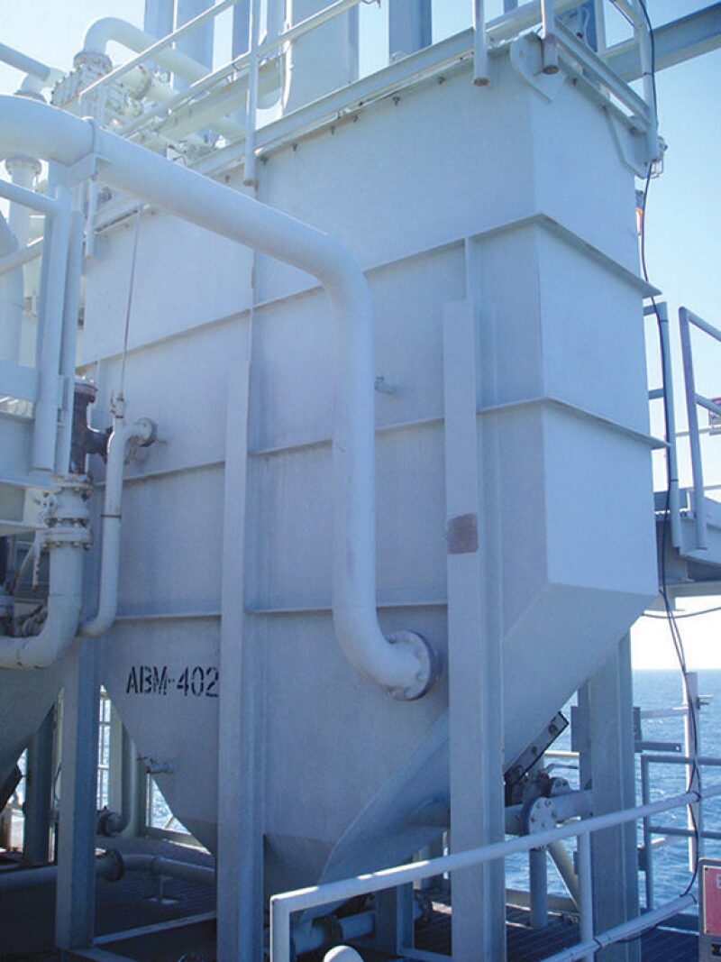
Although the WEMCO unit is still used today, most operators have found alternative methods for similar separation effectiveness. Whereas Monosep modified its design to include a bubble pump, the latest improvement to flotation designs is the Enviro-Cell developed by Enviro‑Tech Systems.
While incorporating many of the design features found in traditional hydraulic equipment, Enviro-Cell offers new features that are important to offshore facilities design and operation. Firstly, the cylindrical design improves structural integrity while simultaneously limiting corrosion that is inherent in the traditional square box. Secondly, the use of multiple eductors to provide increased gasification in each cell translates to improved performance and reduced chemical consumption. Lastly, reduction of the recycle rate has increased retention time within the same physical size and capacity required.
These improvements have increased the efficiency of the hydraulic design, making it comparable to the efficiency of the mechanical design, but the hydraulic design touts lower capital and maintenance costs.
Hydrocyclones and Reconfiguration of IGFs
So far, our discussion has reviewed the advances driven by regulatory requirements. However, further progress was necessary as platform space become more limited and the platform depths deeper. Both of these challenges have brought traditional processing equipment under more scrutiny. In the later 1980s, a new, sleeker method of separation was introduced into the processing train: the hydrocyclone (Fig. 4).
The University of South Hampton, in the UK, developed the principle of using g-force to separate oil, sand, and water. BWN Vortoil introduced the first unit to the Gulf of Mexico by way of field trials. It was billed as the new method to replace conventional separation equipment on offshore platforms.
As the technology advanced, it became a viable solution to improve separation and to better accommodate tight platform space and platform movement. Because the hydrocyclone operates as a pressure vessel, operated liquid-full, platform movement was no longer a concern. Also, the use of liners greatly reduced the footprint of the treatment equipment. It was improved further with the introduction of liners in a vessel instead of in a manifold.
Although the hydrocyclone is a premier method in produced water separation, it has not replaced conventional technology. It serves as a primary separation device, replacing the need for a CPI or skimmer vessel in most cases. Enerscope Systems is the most recent entry into the hydrocyclone market, using multiple inlet ports to create a tight swirl and higher efficiency.
In Canada, a company was working on changing the general configuration of flotation from the traditional horizontal orientation to vertical. This would serve to minimize the space problem and platform movement. Although the design was short-lived, it propelled more successful attempts to meet the new requirements of the offshore industry. The most notable vertical design to meet both criteria for platform space and movement was the Unicel developed by John Cairo, a friend and competitor.
His Unicel design changed the flotation cell market in a significant way. He successfully placed his equipment offshore in many locations, thereby allowing for retrofits of older equipment in its existing space. This design also served the new equipment market well because of its practical pricing and reduced size.
An important point is its effectiveness at full design capacity. There are several installations where the vertical IGF is unable to reach full capacity at the required discharge ppm due in part to reduced retention times. The vertical design does not offer sufficient length/width ratio as does a horizontal configuration. This inherent design problem becomes fully accentuated at capacities of 50% or more. Although the vertical IGF can sometimes meet full capacity at the required discharge, increased chemical consumption detracts from its flare.
Although meeting space requirements becomes more daunting with traditional horizontal IGF designs, overall size has been reduced because of design improvements, i.e., reduced recirculation rates. The addition of internal sloshing baffles and deflection plates help to mitigate platform movement effects. Although there is no comparison of efficiency between the horizontal design and the vertical design, both have a place in the oil and gas industry.
The need for reduced size and increased efficiency continues to drive the development of the next generation of IGFs. A concept now being tested is a compact flotation unit (CFU), which requires little or no retention time to remove the oil and grease. Relying primarily on the sparging/flotation process, the CFU leaves no room for error. If the separation technique fails for any reason, fluids with increased ppm content will be discharged into the ocean. Filters downstream of the CFU must be installed as a backup to the system in case of equipment failure.
Today, we are more than 30 years from the first installation of the IGF cell and more than 40 years from that of the CPI. In many cases, this is still the most accepted technology for the most efficient separation. Hopefully in the near future, the perfect method of combining maximum efficiency along with space savings and platform movement control will be invented.
From all indications, the industry is moving toward the elimination of all topside equipment and placing the full process on the sea floor. This will eliminate the space and movement problems and may increase the efficiency of present day separation designs.
Advances in Monitoring of Effluent Discharge
The technologies for the monitoring of effluent discharges from processing have also made major strides. The policing of our own industry has been ongoing for more than 10 years, but it met with operational problems, high maintenance, and inaccuracy. Within the past 5 years, however, an oil in water monitor billed as maintenance-free has emerged and it has surpassed other market entries in accuracy and ease of use.
Developed by Advanced Sensors, the monitor uses laser and fluorescence along with a patented ultrasonic lens cleaning technique. The company is improving the technology by adding a spectrometer to detect a full range of hydrocarbons and video microscopy, a near streaming video of the process, lets the operator “fingerprint” the water with accuracy, thus allowing the operator to effectively monitor and comply with discharge limits. In the latest attempt of defining the process, the mass spectrometer will be launched in the near future.
Tertiary treatment has also advanced. Nutshell filters are generally perfected, but specially coated filter media (MyCelx) are a likely next-generation method of final treatment, delivering effluent discharges with levels of 1 ppm or less.
The demonstration of proven capabilities to meet more stringent discharge requirements will be important as well as verification through accurate and maintenance-free monitoring. Using the best available technology is the most accepted method of proving our ability to meet the current and future discharge requirements.